Welcome to
Azur Electronics
Azur Electronics
REPAIR HP 3764A DIGITAL
TRANSMISSION ANALYSER
TRANSMISSION ANALYSER
Home
Projects
Test Equipment
- Accessories
- Adaptors
- Amplifiers
- Attenuators
- Cables
- Frequency Counters
- Logic Analysers
- Multi-Meters
- Network Analysers
- Oscilloscopes
- Power Meters
- Power Supplies
- Prototyping Equipment
- Signal Generators
- Spectrum Analysers
- Tools
Operating Information
- Operating HP 141T
- Operating HP 1630D
- Operating HP 8175A
- Operating HP 8407A
- Operating HP 8410C
- Operating HP 8552B IF Section
- Operating HP 8553B RF Section
- Operating HP 8554B RF Section
- Operating HP 8555A RF Section
- Operating HP 8556A LF Section
- Operating HP 8594E Spectrum Analyser
- Operating HP 8901B
- Operating LeCroy 9310
Technical
- Allen Key Sizes
- High Voltage Measurement
- HP Cases
- HP Information
- HP-IB Interface Bus
- Measurement Units
- Motorola ECL
- RF Connectors
- RF Power - Voltage Conversion
For Sale
Wanted
Links
About Me
Contact Me
Site Map
August 2020
The first 3764A (#1) was bought in 2010 and had several assemblies missing so was not repairable. This was an early 3764A S/N 2322 circa 1983 at the start of production and is identified by the (missing) internal printer.
The second 3764A (#2) is complete and is S/N 3228 circa 1992 near the end of production. This has Option 007 instead of the printer.
The foam insert in the fan cover had disintergrated and spread itself all over the inside. The HP 3764A requires a complete strip down to assembly level to clean-up and inspect.
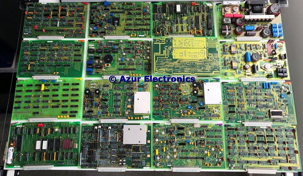
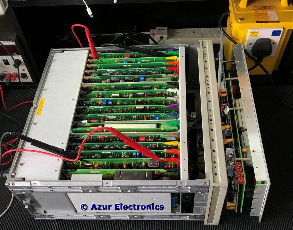
The complete 16 Plug-In Assemblies
An extra A23 Assembly for Option 007 behind the front panel
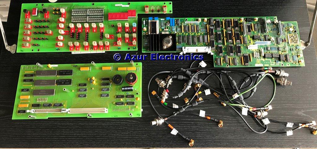
A21, A22 & A23 Assemblies and coax cables behind the front panel
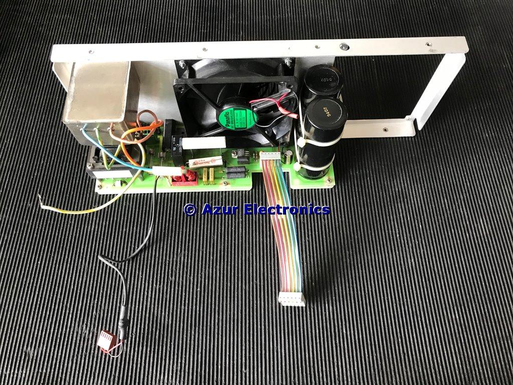
A24 Power Supply Assembly behind the rear panel
DANGER: exposed mains voltages on pcb!
DANGER: exposed mains voltages on pcb!
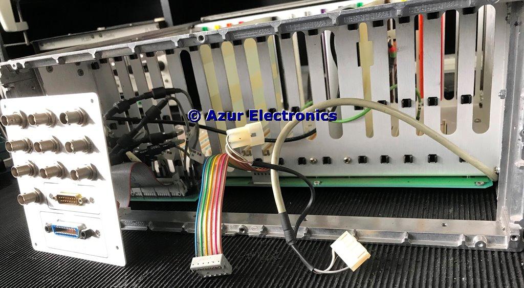
Rear Connector Panel and cables behind the rear panel
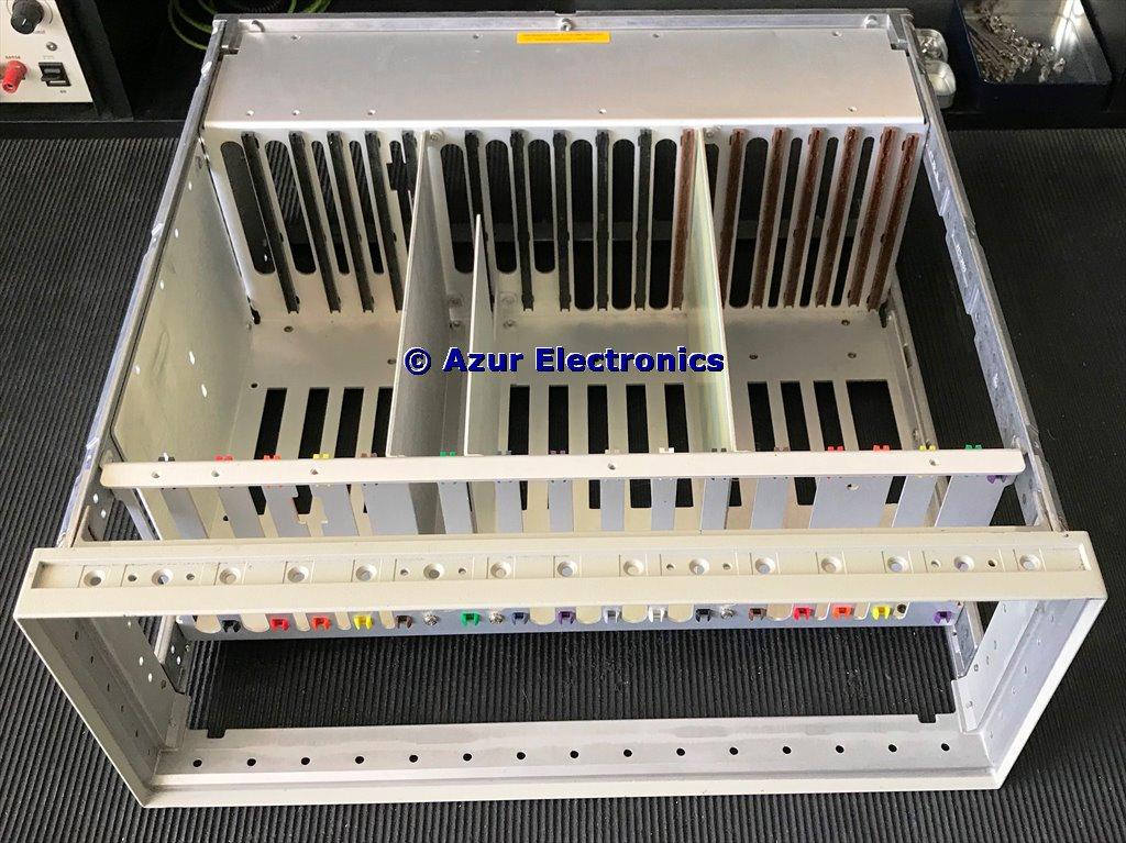
The end result, stripped down to Chassis
There are quite a few differences between the original #1 assemblies and the later #2 ones. The Service Manual is for up to S/N 2615 and does not reflect all the changes. I will search for later Manual Updates although probably unlikely to find anything.
September 2020
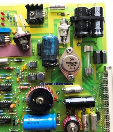
The only obvious damage on the 16 plug-in assemblies was an unusual 3 leg axial electrolytic capacitor on A2 Power Supply.
Replaced with a conventional 2 leg electrolytic capacitor.
The only obvious damage on the 16 plug-in assemblies was an unusual 3 leg axial electrolytic capacitor on A2 Power Supply.
Replaced with a conventional 2 leg electrolytic capacitor.
Powered-up very slowly to 230Vac with just the Power Supply Assemblies fitted: A0, A2 and A24. The fan is running and all 4 red LEDs are on. Voltage rails are: -5V on A0; +12V -15V +15V +5V on A2. The 15V rails are both low so fault finding required.
This is a surprisingly complex power supply design which HP seemed partial to designing! Annoyingly there are several closed loops between the 3 PCB's which makes isolating the fault difficult, plus it would help if I had the correct circuits!
IMHO a very poor design and PCB layout. It must have been challenging to build for production and test.
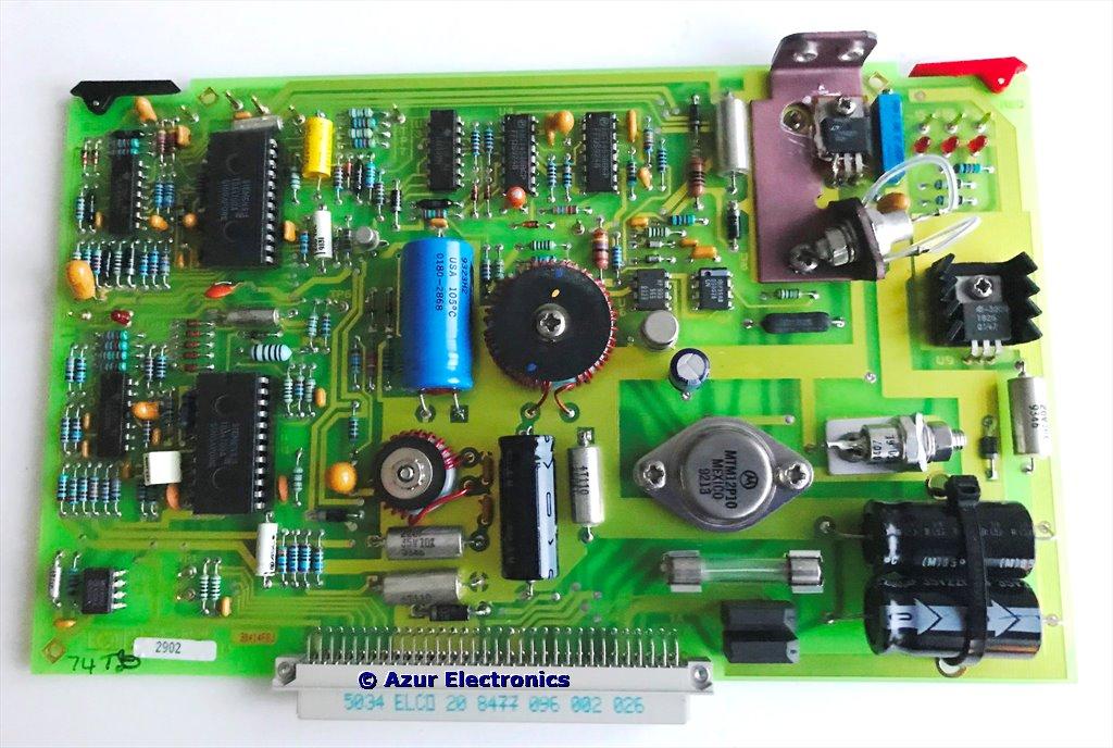
A2 Power Supply with TDA4700 24 pin IC's
November 2020
A0 is a SMPS (Switched Mode Power Supply) which receives 320Vdc from A24. The switching FETs need a +ve & -ve gate drive signal from A2. The resultant ac signal is fed via a switching transformer to rectifier circuits. The ±5V & ±24V are then fed to A2 where the ±5V is output and the ±24V is converted to ±15V outputs and +12V & +2.5V rails. This design is based on two 24 pin Siemens TDA4700 Control ICs which provide the gate drive signals for A0 and the +15V gate drive for A2.
There must have been much easier ways of providing the ±5V & ±15V outputs!
Frustratingly there was no actual faulty component. The parameters for the TDA4700 IC's were at variance with the circuit. Some minor changes to circuit values solved the problem. Possibly original components had aged and were out of tolerance causing the failure. A very time consuming exercise!
Testing 3764A
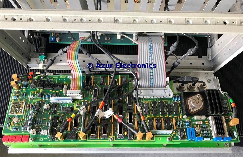
Refitted all the boards and the front panel assembly, one at a time, monitoring the ac mains current and dc voltage rails in case of more problems. Also the 3764A is connected via a Mains Power Isolating Transformer for safety. The A0 Power Supply normally has its heat sinks screwed to the side panel for thermal dissipation.
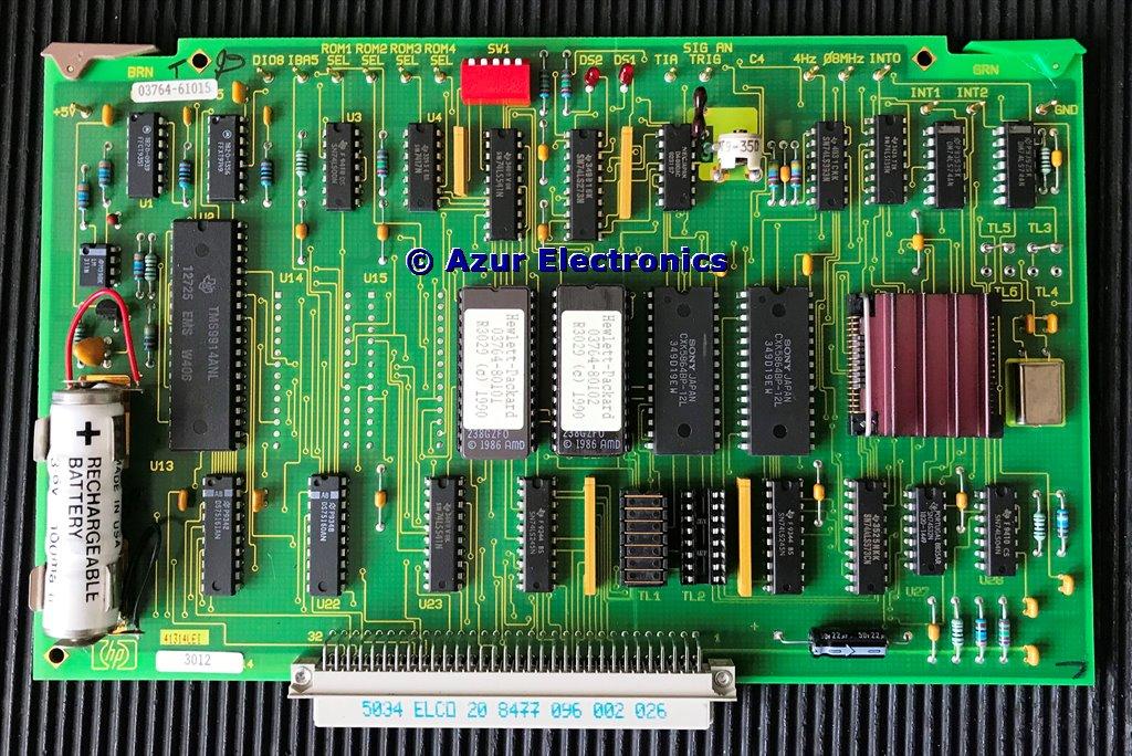
A15 Processor with Battery
There is a 3.6V 100mA/h battery on A15 Processor which has discharged to 1.2V so will need recharging or maybe replacing. Recharged ok after a couple of hours use.
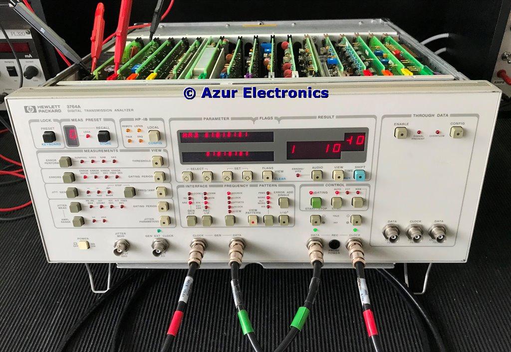
Testing 3764A
Working through the Operating Manual and the 3764A appears to be working correctly.
Rate Fixed 1 is 155.520MHz instead of the standard 139.264MHz. Maybe this is Option J31. This is probably for a special SONET (Synchronous Optical Networking) frequency. Rate Variable 1 & 2 can be set to any frequency from 1kHz to 170MHz, or an external clock source can be used.
Surprisingly the date is not Y2K (Year 2000) compliant so is stuck in the 1900's!