Welcome to
Azur Electronics
Azur Electronics
PROTOTYPING EQUIPMENT
Home
Projects
Test Equipment
- Accessories
- Adaptors
- Amplifiers
- Attenuators
- Cables
- Frequency Counters
- Logic Analysers
- Multi-Meters
- Network Analysers
- Oscilloscopes
- Power Meters
- Power Supplies
- Prototyping Equipment
- Signal Generators
- Spectrum Analysers
- Tools
Operating Information
- Operating HP 141T
- Operating HP 1630D
- Operating HP 8175A
- Operating HP 8407A
- Operating HP 8410C
- Operating HP 8552B IF Section
- Operating HP 8553B RF Section
- Operating HP 8554B RF Section
- Operating HP 8555A RF Section
- Operating HP 8556A LF Section
- Operating HP 8594E Spectrum Analyser
- Operating HP 8901B
- Operating LeCroy 9310
Technical
- Allen Key Sizes
- High Voltage Measurement
- HP Cases
- HP Information
- HP-IB Interface Bus
- Measurement Units
- Motorola ECL
- RF Connectors
- RF Power - Voltage Conversion
For Sale
Wanted
Links
About Me
Contact Me
Site Map
After designing the theoretical circuit, my method of prototyping is to build the circuit on a plug-in breadboard using wire links to make the inter-connections. The Thurlby PL320 is used to provide dc power the breadboard. This provides a convenient method of setting dc voltage and monitoring or limiting the current.
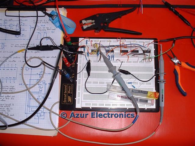
Prototyping Breadboard
I tend to build one stage at a time, record the results and modify the circuit if required. This also gives me the opportunity to experiment a bit with new chips to see what they can do. These breadboards work fine on lower frequency work, typically 74 series logic circuits. Obviously at higher RF frequencies the stray capacitance and inductance would make breadboards unusable, so printed circuit boards with RF ground screens would be required.
When the circuit is finalised, I draw it on graph paper. Next stage is to build the circuit on a 'Vero Stripboard', which is a matrix board with holes at a 2.5mm (0.1") pitch and copper strips in only one direction, which can be cut as required. I design the layout on graph paper at 2x scale with components in black, copper strips in blue and discrete wiring in red. This is a fairly crude method but an inexpensive way of laying out a prototype. This makes the actual construction easier and avoids layout problems, but it can still be very time consuming. Wherever possible, I try to make use of parts that I already have. I prefer to use IC sockets, but before fitting the IC's 'buzz-out' all the wiring with an Ohmmeter to check for errors.
When the circuit is finalised, I draw it on graph paper. Next stage is to build the circuit on a 'Vero Stripboard', which is a matrix board with holes at a 2.5mm (0.1") pitch and copper strips in only one direction, which can be cut as required. I design the layout on graph paper at 2x scale with components in black, copper strips in blue and discrete wiring in red. This is a fairly crude method but an inexpensive way of laying out a prototype. This makes the actual construction easier and avoids layout problems, but it can still be very time consuming. Wherever possible, I try to make use of parts that I already have. I prefer to use IC sockets, but before fitting the IC's 'buzz-out' all the wiring with an Ohmmeter to check for errors.
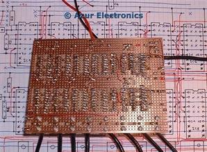
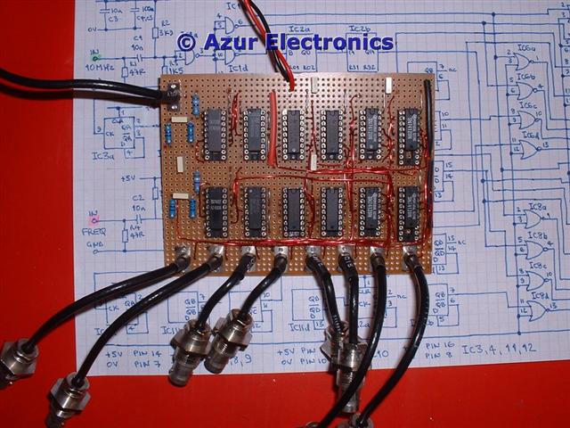
Prototype PCB - not pretty but it works!
The alternative is CAD (Computer Aided Design), there are many PCB Layout packages that will produce all the information necessary to enable a professionally manufactured pcb. This would be necessary if you were going to manufacture a batch of pcb's. Even so a prototype pcb is required to test the circuit. In my experience there is always something that needs modifying!
June 2013
I'm now using DesignSpark PCB CAD software from RS Components. This provides projects, schematics, PCB layout and 3D modelling. The learning curve is quite a challenge but well worth while persevering with.
June 2013
I'm now using DesignSpark PCB CAD software from RS Components. This provides projects, schematics, PCB layout and 3D modelling. The learning curve is quite a challenge but well worth while persevering with.