
Welcome to
Azur Electronics
Azur Electronics
Home
Projects
Test Equipment
- Accessories
- Adaptors
- Amplifiers
- Attenuators
- Cables
- Frequency Counters
- Logic Analysers
- Multi-Meters
- Network Analysers
- Oscilloscopes
- Power Meters
- Power Supplies
- Prototyping Equipment
- Signal Generators
- Spectrum Analysers
- Tools
Operating Information
- Operating HP 141T
- Operating HP 1630D
- Operating HP 8175A
- Operating HP 8407A
- Operating HP 8410C
- Operating HP 8552B IF Section
- Operating HP 8553B RF Section
- Operating HP 8554B RF Section
- Operating HP 8555A RF Section
- Operating HP 8556A LF Section
- Operating HP 8594E Spectrum Analyser
- Operating HP 8901B
- Operating LeCroy 9310
Technical
- Allen Key Sizes
- High Voltage Measurement
- HP Cases
- HP Information
- HP-IB Interface Bus
- Measurement Units
- Motorola ECL
- RF Connectors
- RF Power - Voltage Conversion
For Sale
Wanted
Links
About Me
Contact Me
Site Map
OPERATING HP 8410C
NETWORK ANALYSER
NETWORK ANALYSER
February 2011
Understanding the HP 8410C Network Analyser is my second attempt at using network analysis, after the HP 8407A Network Analyser. Most of my test equipment is fairly easy to use and I have had previous experience with similar items and their applications. Network Analysers are one (of the many) areas where I have little knowledge, although I appreciate their general function, so these are my working notes.
Understanding the HP 8410C Network Analyser is my second attempt at using network analysis, after the HP 8407A Network Analyser. Most of my test equipment is fairly easy to use and I have had previous experience with similar items and their applications. Network Analysers are one (of the many) areas where I have little knowledge, although I appreciate their general function, so these are my working notes.
HP 8410C Network Analyser
The HP 8410C Network Analyser operates over a frequency range from 110MHz to 18GHz and effectively extends the range of the HP 8407A Network Analyser which covers the band 100kHz to 110MHz. At these higher microwave frequencies everything starts to have a greater effect on the performance of the system. Connectors, cables, power splitters, attenuators, all must all be capable of operating up to 18GHz.
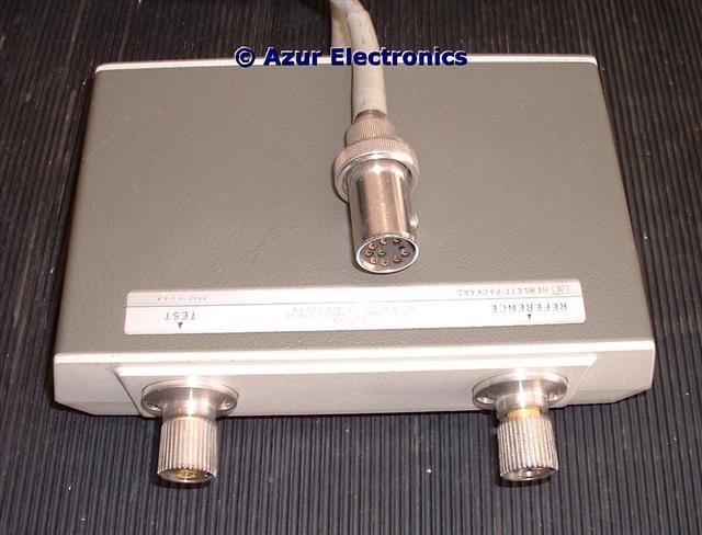
HP 8411A Harmonic Frequency Converter
The 8410C needs the HP 8411A Harmonic Frequency Converter as its front end.
This converts the two input signals, Reference and Test, to 278kHz phase-locked signals for analysis. The 8411A needs very careful handling to avoid static damage and overloading the inputs. The connectors are hermaphrodite APC-7 and therefore require APC-7 to N-type adaptors. When not in use, the 8411A should have both inputs terminated with 50Ω N-type terminations.
This converts the two input signals, Reference and Test, to 278kHz phase-locked signals for analysis. The 8411A needs very careful handling to avoid static damage and overloading the inputs. The connectors are hermaphrodite APC-7 and therefore require APC-7 to N-type adaptors. When not in use, the 8411A should have both inputs terminated with 50Ω N-type terminations.
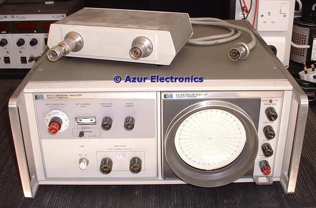
HP 8410C, 8411A (with one adaptor) & 8414A Display
The 8410C based Network Analyser System is still considered to be excellent test equipment for microwave circuit design and testing. It is also relatively straightforward to maintain with complete Operating and Service Manuals available, unlike more modern microprocessor-based systems.
Even so, network analysis at microwave frequencies is a complex subject. The HP Operating and Service Manual for the HP 8410B and Manual Supplement for HP 8410C does not provide much information on operating techniques. An internet search for HP8410, HP8410A, HP8410B & HP8410C provides a number of really useful documents. HP Application Note 177-1 Network Analyzer Applications http://hpmemoryproject.org/an/pdf/an_117-1.pdf is essential. Mark Kahrs paper on Owning and Operating the HP 8410 Network Analyzer http://kahrs.us/~mark/pdf/papers/mud2k.pdfis is also very helpful.
Even so, network analysis at microwave frequencies is a complex subject. The HP Operating and Service Manual for the HP 8410B and Manual Supplement for HP 8410C does not provide much information on operating techniques. An internet search for HP8410, HP8410A, HP8410B & HP8410C provides a number of really useful documents. HP Application Note 177-1 Network Analyzer Applications http://hpmemoryproject.org/an/pdf/an_117-1.pdf is essential. Mark Kahrs paper on Owning and Operating the HP 8410 Network Analyzer http://kahrs.us/~mark/pdf/papers/mud2k.pdfis is also very helpful.
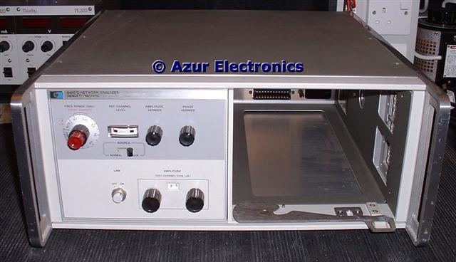
The HP 8410C Network Analyser System front view
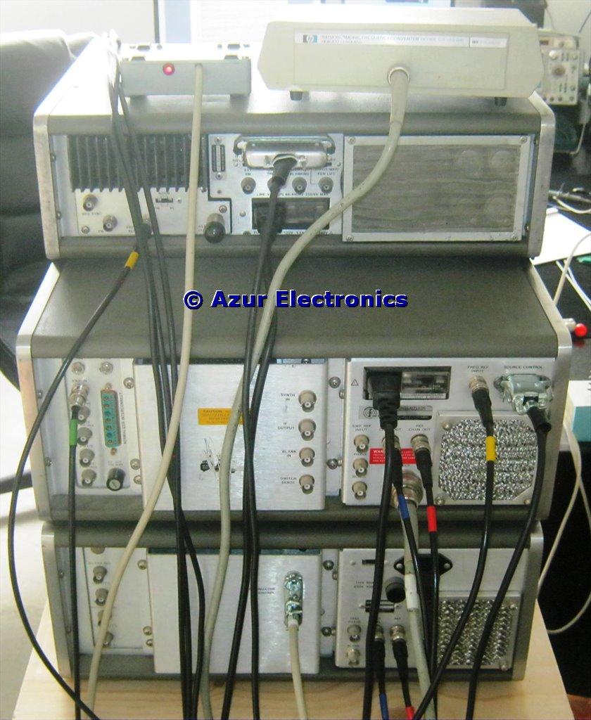
The HP 8410C Network Analyser System rear view
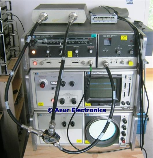
The 8410C Network Analyser System comprises:
HP 8411A Harmonic Frequency Converter
2 APC-7 to N-type Adaptors
Azur ACU109 Attenuator Control Unit
HP 8620C Sweep Generator
HP 8120-2208 Source Control Cable
HP 86222A RF Plug-In and HP 86290B RF Plug-In
HP 8410C Network Analyser
HP 8412B Phase - Magnitude Display
HP 8418A Auxilliary Display Holder
HP 8414A Polar Display
HP 11667A Power Splitter
and various BNC and N-type cables
The HP 8413A Phase - Gain Indicator could also be used as a display unit.
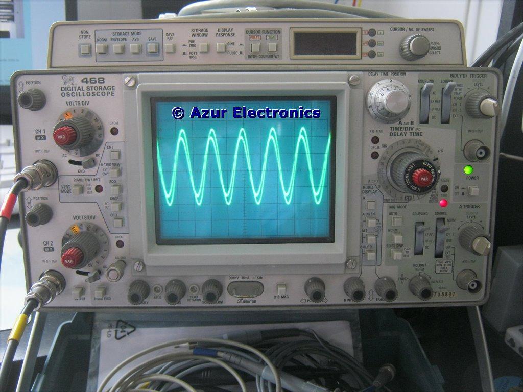
278kHz Reference and Test signals
displayed on an Oscilloscope
displayed on an Oscilloscope
On connecting up the system and ensuring that the Ref Channel Level meter has a signal in the Operate range, check that the rear panel Ref Chan Out and Test Chan Out both have 278kHz signals on an Oscilloscope. Check that the Amplitude Vernier, Phase Vernier and Amplitude Test Channel gain controls modify the outputs.
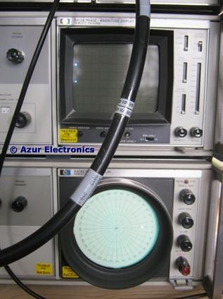
Setting-up the 8412B and 8414A with CW signals
Before attempting swept measurements, I generate a CW signal in turn at the two ends of the frequency range that I want to sweep. The 8412B can then be adjusted for horizontal gain and position to set the limits at each end of the scale. Similarly the 8414A can be adjusted for 0° and the correct attenuation on my ACU109 Attenuator.
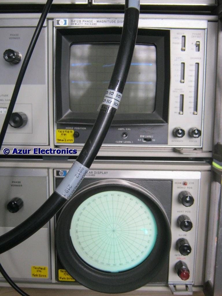
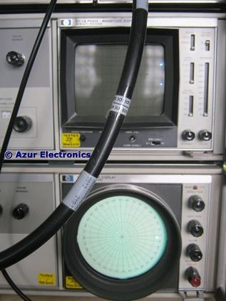
Swept response with the 8412B and 8414A
Next I confirm that the full swept measurement is displayed correctly. Now the Device Under Test (DUT) can be connected into the test channel between the power splitter and the 8411A.
I have not attempted to detail the various reflection and transmission S-parameter measurements. HP Application Note 117-1 is the definitive document for this subject.
Happy RF engineering!
I have not attempted to detail the various reflection and transmission S-parameter measurements. HP Application Note 117-1 is the definitive document for this subject.
Happy RF engineering!
August 2019
All the 8407A & 8410C based Network Analyser System has now been Sold.
All the 8407A & 8410C based Network Analyser System has now been Sold.