
Welcome to
Azur Electronics
Azur Electronics
Home
Projects
Test Equipment
- Accessories
- Adaptors
- Amplifiers
- Attenuators
- Cables
- Frequency Counters
- Logic Analysers
- Multi-Meters
- Network Analysers
- Oscilloscopes
- Power Meters
- Power Supplies
- Prototyping Equipment
- Signal Generators
- Spectrum Analysers
- Tools
Operating Information
- Operating HP 141T
- Operating HP 1630D
- Operating HP 8175A
- Operating HP 8407A
- Operating HP 8410C
- Operating HP 8552B IF Section
- Operating HP 8553B RF Section
- Operating HP 8554B RF Section
- Operating HP 8555A RF Section
- Operating HP 8556A LF Section
- Operating HP 8594E Spectrum Analyser
- Operating HP 8901B
- Operating LeCroy 9310
Technical
- Allen Key Sizes
- High Voltage Measurement
- HP Cases
- HP Information
- HP-IB Interface Bus
- Measurement Units
- Motorola ECL
- RF Connectors
- RF Power - Voltage Conversion
For Sale
Wanted
Links
About Me
Contact Me
Site Map
OPERATING HP 8175A
DIGITAL SIGNAL GENERATOR
DIGITAL SIGNAL GENERATOR
The HP 8175A Digital Signal Generator can provide programmable data patterns of: 24 parallel channels, or 2 serial channels; and 2 independent analog arbitrary waveform outputs. It can interact with the device under test using triggers and flags. It can be used with the similar to operate HP 1630D Logic Analyser.
This HP 8175A Digital Signal Generator was manufactured circa 1989 and by today’s standards is probably totally obsolete, even though it cost almost $20K! For my purposes it is an excellent TTL/CMOS/ECL digital generator, with the added Option 001 Fine Timing and Option 002 Arbitrary Waveform Generator for analogue 50Ω outputs, even if it is some 30+ years old.
This HP 8175A Digital Signal Generator was manufactured circa 1989 and by today’s standards is probably totally obsolete, even though it cost almost $20K! For my purposes it is an excellent TTL/CMOS/ECL digital generator, with the added Option 001 Fine Timing and Option 002 Arbitrary Waveform Generator for analogue 50Ω outputs, even if it is some 30+ years old.
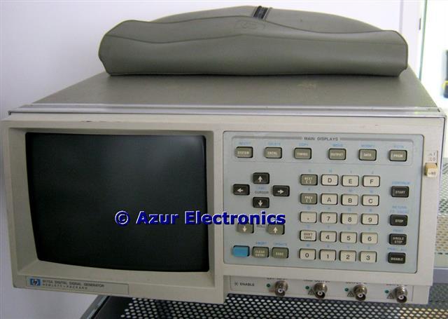
Front Panel showing push-button controls
April 2022
The downloaded Operating and Programming Manual of May 1985 (includes Option 001) and the Option 002 Operating and Programming Manual of May 1986 are very comprehensive. Reading through these Manuals and taking new photos where necessary will give me a lot more expertise. The 8175A is a complex and versatile beast, so these are my working notes.
[With acknowledgement and thanks to HP for reproducing some text from their Manuals]
POWER ON
Power On - the cooling fans start and the 4 Green LEDs next to the Front Panel BNC connectors illuminate. An automatic self-test routine is performed, either standard or extended depending on Rear Panel switch setting. If any failure is detected an appropriate error message will be displayed. On completion of the tests the System Page [Configuration] is displayed.
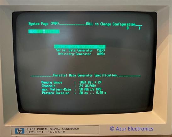
PARALLEL DATA GENERATOR
At power on, the default configuration setting is Parallel Data Generator as above.
Specification is:
Memory Space: 1024 Bit x 24
Channels: 24 (8 per Pod 0, 1 & 3)
Max Pattern Rate: 50MBit/s NRZ
Pattern Duration: 20ns to 9.99s
Specification is:
Memory Space: 1024 Bit x 24
Channels: 24 (8 per Pod 0, 1 & 3)
Max Pattern Rate: 50MBit/s NRZ
Pattern Duration: 20ns to 9.99s
RECALL STANDARD SETTINGS
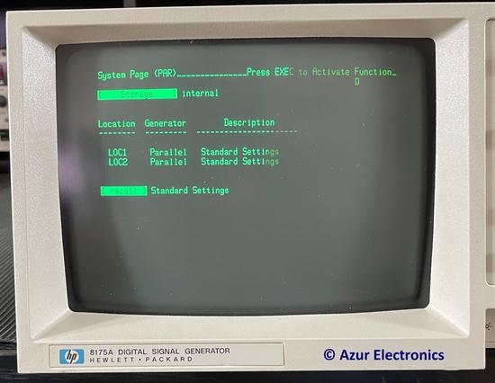
Recall Standard Settings - to start with a set of known parameter values and operating conditions.
Press SYSTEM key, then NEXT until [Storage] internal menu is displayed.
Press CURSOR key to position the cursor in the storage function field.
Press NEXT key until [recall] Standard Settings is displayed.
Press EXEC key to activate.
NOTE: all data is set to 0.
Press SYSTEM key, then NEXT until [Storage] internal menu is displayed.
Press CURSOR key to position the cursor in the storage function field.
Press NEXT key until [recall] Standard Settings is displayed.
Press EXEC key to activate.
NOTE: all data is set to 0.
SETTING UP DATA PATTERNS
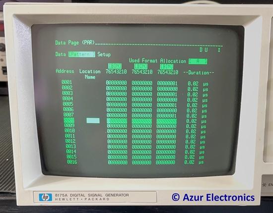
Setting Up Data Patterns – for up to 24 Pod Channels (for Parallel), or 2 Pod Channels (for Serial).
Press DATA key, then NEXT until Data [Pattern] Setup menu is displayed.
Press ROLL up key to Address 0001.
Press CURSOR down key to move to Address 0001 field.
Press CURSOR right key to move to Channel 0 of Pod 0, at extreme right hand side of display.
NOTE: Pod 2 is left column, Pod 1 is middle column, Pod 0 is right column. Each has 8 channels: 7 to 0 displayed in BINary format. OCTal, DECimal or Denary and HEXadecimal formats are also available.
Press 1 key to set a logic 1 output, the display will auto-roll to Address 0002 field.
Press CURSOR right key to move to Channel 0 of Pod 0.
Press 0 key to set a logic 0 output, the display will auto-roll to Address 0003 field.
NOTE: 0 is the default setting, but will not auto-roll unless set.
Press ROLL up key (if 0 not set) to Address 0003 and CURSOR right key to move to Channel 0 of Pod 0.
Press 1 key to set a logic 1 output, the display will auto-roll to Address 0004 field.
Similarly using ROLL up key to next Address and CURSOR right key to move to Channel 0 of Pod 0.
Set the remaining addresses to program the 8 bits of Channel 0 Pod 0 to 01010101 for addresses 0000 to 0007.
NOTE: The remaining addresses 0008 to 1023 will all be set at 0.
NOTE: the top right of the display shows D and U.
D indicates that the Pod outputs are currently Disabled.
U indicates that an Update is required.
OUTPUT DATA PATTERNS
To output a data pattern, certain preconditions have to be met.
Press CNTRL key, then CURSOR down to Mode [Single Cycle], then NEXT to change Mode to [Auto Cycle]. Otherwise only a single cycle of data will be output.
Press PRGM key, then CURSOR down then right to change end address to 0007. Otherwise all addresses from 0000 to 1023 will be output.
Press OUTPUT key, then NEXT to change Output Pods to [enabled].
NOTE: removes the D at top right being displayed.
Press (blue) SHIFT key and EXEC to update.
NOTE: removes the U at top right being displayed.
NOTE: removes the D at top right being displayed.
Press (blue) SHIFT key and EXEC to update.
NOTE: removes the U at top right being displayed.
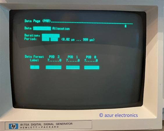
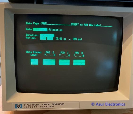
The default bit rate is 0.02µs (50Mbps), to change this to 1µs (1Mbps) Press DATA key, then NEXT until Data [Format] Allocation Setup menu is displayed.
Press CURSOR down key to move to Period field. Press 1.00 keys to set a logic 1µs period.
Press CURSOR down key to move to Period field. Press 1.00 keys to set a logic 1µs period.
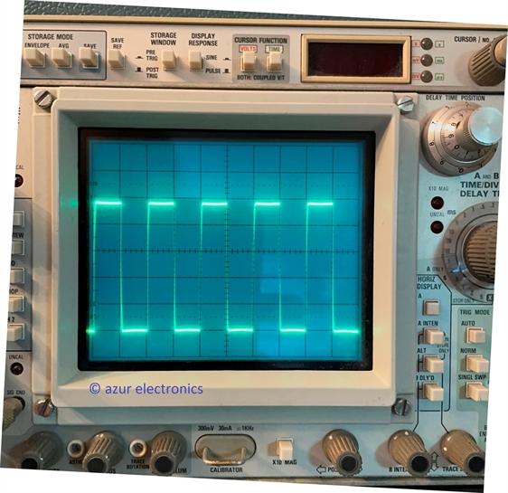
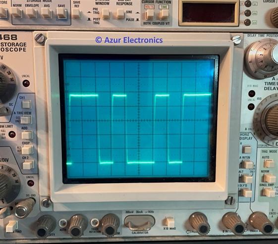
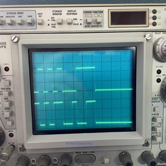
Connect the Pod 0, Channel 0 output to an Oscilloscope using the HP 15408A Plug-On Grabber and Ground Lead. Set volts to 1V/div and timebase to 1µs/div. This will display the output, initially 0V.
Press START and the parameters set up on the 8175A will now display an output of the TTL square wave pattern of 1µs for each bit.
This example generates a square wave of 2µs period with an equal mark-space ratio of 1µs. It is possible to generate a 0.01µs pulse in every 10.24µs, or a 9.99s pulse in every 10229s (170minutes), and any pattern in between.
March 2023
INPUT / OUTPUT PODS
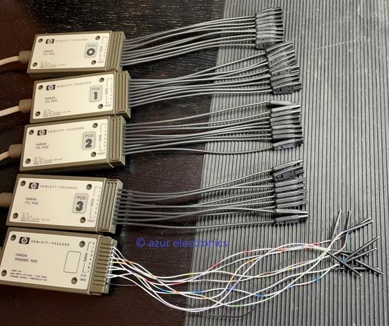
There are 5 Pods in normal operation, 4 Data Pods and 1 Trigger Pod.
In this setup there are 4 TTL Data Pods HP 15464A and 1 Trigger Pod HP 15463A.
Alternatives for the Data Pods are: TTL/CMOS HP 15462A and ECL HP 15461A.
Pod 0 outputs data chanels 0 to 7, Pod 1 outputs data channels 8 to 15, Pod 2 outputs data channels 16 to 23. Pod 3 outputs flags and clock. Trigger Pod inputs flags and triggers.
Pods 0, 1, 2, 3 have a TRIST input, this disables the Pod and sets the outputs to a Tri-State high impedance condition.
It is possible to connect another 8175A in a Master/Slave configuration to provide an additional 24 data channels.
CLOCK OUTPUT
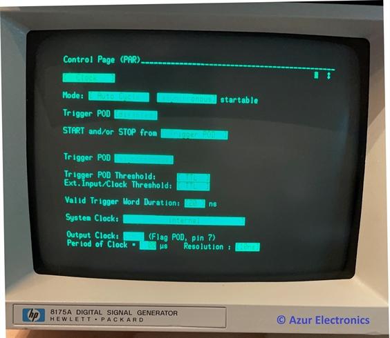
To output the clock signal press STOP if neccessary. Press CNTRL then press NEXT until [Clock] menu is displayed. Press CURSOR DOWN key to position the Cursor in Output Clock field. Press NEXT to change from OFF to ON. Press CURSOR DOWN key to position the Cursor in the Period of Clock field,press 1.00 keys to set a logic 1µs period, or as required. Press START and the Clock Signal will be output on Pod 3 pin 7.
CHANGE DATA PATTERNS
Before any parameters can be changed, press STOP to halt the 8175A output. Parameters can now be amended as required.
Other data formats can be added without removing previous ones.
As an example, just using 1 Pod Channel and a short sequence.
Press DATA key then NEXT to Data [Format] Allocation.
Cursor to Data Format Label field, currently showing 'A'.
Press (blue) SHIFT key and INSERT key.
Press B to label new field.
Cursor right to Channel 1 of Pod 0.
Press NEXT to change '.' to '*' to activate channel.
Press DATA then NEXT to Data [Pattern] Setup.
Cursor to Used Format Allocation,
Press NEXT to change 'A' to 'B'.
Set data for addresses 0001 to 0007 to 1101001.
Press (blue) SHIFT key and EXEC to update.
Press START to output.
Cursor to Used Format Allocation,
Press NEXT to change 'A' to 'B'.
Set data for addresses 0001 to 0007 to 1101001.
Press (blue) SHIFT key and EXEC to update.
Press START to output.
TIMING DIAGRAMS
An alternative way of inputting data patterns is to use the data waveform setup. In this example using the previous 01101001 pattern and change it to 00010111.
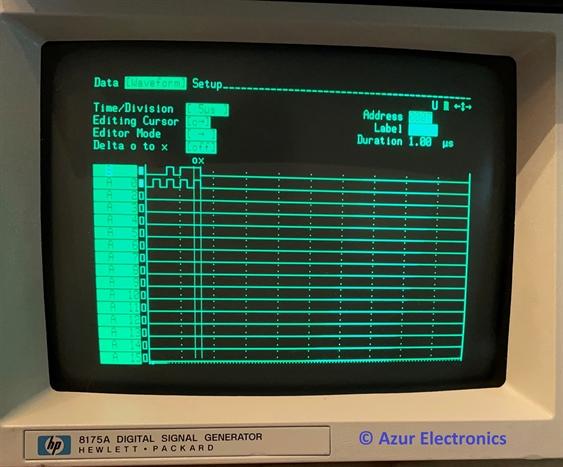
Press DATA key then NEXT to Data [Waveform] Setup.
Cursor to Time/Division field.
Press NEXT to change the value to 5µs (50ns to 5s available).
Cursor to Address field.
Enter address of 0000 which is START label.
To move the label B waveform to the top:
Cursor to A0 field, press PREVIOUS twice.
Cursor to Editor Mode field.
Press NEXT to change to ->.
This keeps the the Cursor in horizontal plane when editing, instead of moving vertically down after each editing operation.
Cursor to B labelled waveform line.
Press Cursor one time to address 0001.
Press 0 and data changes from 1 to 0.
Press 0010111 to complete change.
This is for a fixed duration data pattern, in this example 1µs.
Press (blue) SHIFT key and EXEC to update.
Press START to output.
VARIABLE DURATION TIMING DIAGRAMS
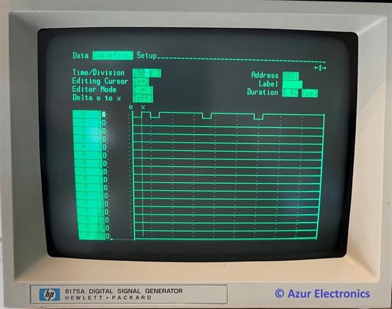
Waveform patterns which include very short data durations combined with long steady state conditions are best setup with variable duration.
Press DATA then NEXT twice to Data [Format] Menu.
Move Cursor to Duration field, press NEXT to change Fixed to Variable. This results in the duration being set to the default value of 0.02µs (change if required).
Press DATA then NEXT twice to Data [Waveform] Setup field.
Move Cursor to Time/Division field, change to 50ns.
Move Cursor to Editor Mode field, change to ->
Move Cursor to A0 label line.
Move Cursor right one time (this is address 0001).
Enter data pattern 1010101.
Move Cursor left to address 0003.
Move flashing Cursor to Duration field, currently showing 0.02µs. Change to 0.1µs.
To change the next duration value, change the address to 0005 by pressing the ROLL <- key. (An alternative is to move the flashing Cursor to the Address field and change the address to 0005, then move back to the Duration field).
Change the duration to 0.08µs.
Press the ROLL -> key to display the complete waveform.
Press (blue) SHIFT key and EXEC to update.
Press START to output.
NOTE: With variable duration waveforms it is recommended to set the complete data pattern first all with the same duration, then change the individual address durations as required.
MENU MAPS
Menu Maps are provided in the Operating and Programming Manual (OPM) 08175-90006 of May 1985 on pages 50 to 53. These show the menus and sub menus.
Brief information on this and other Manual contents follows, for more details read the Manual!
The six main menu keys are:
SYSTEM sub pages: Configuration, Peripherals, Storage.
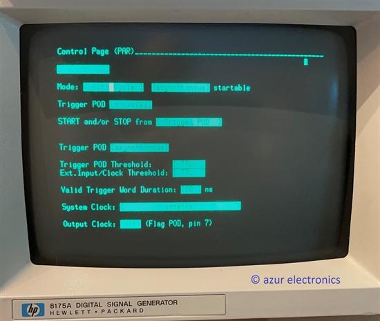
CONTROL sub pages: Clock, Input, Flag, Simulate.
Provides setup information for 15463A Trigger Pod for input triggers, output flags, tristate operation.
TIMING sub pages: Fine Timing Off or On (Option 001).
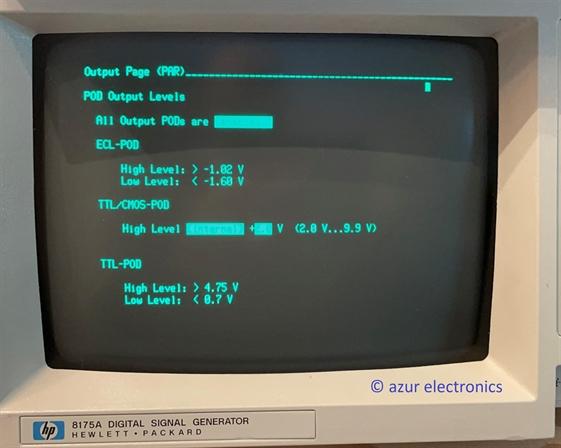
OUTPUT page: Output.
Setup information for output Pods.
DATA sub pages: Format, Pattern, Waveform.
To setup, edit and display data.
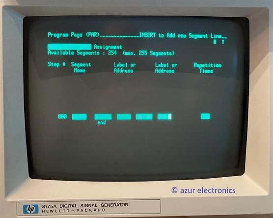
PROGRAM sub pages: Trigger Event, Module.
Enables pattern sequencing to be defined.
As well as the six main menus, editing functions are also available (pages 96-110). These mainly affect the DATA and PROGRAM pages.They are accessible using the blue SHIFT key and INSERT, DELETE, COPY, MOVE, MODIFY, FCTN.
Brief information on this and other Manual contents follows, for more details read the Manual!
The six main menu keys are:
SYSTEM sub pages: Configuration, Peripherals, Storage.
CONTROL sub pages: Clock, Input, Flag, Simulate.
Provides setup information for 15463A Trigger Pod for input triggers, output flags, tristate operation.
TIMING sub pages: Fine Timing Off or On (Option 001).
OUTPUT page: Output.
Setup information for output Pods.
DATA sub pages: Format, Pattern, Waveform.
To setup, edit and display data.
PROGRAM sub pages: Trigger Event, Module.
Enables pattern sequencing to be defined.
As well as the six main menus, editing functions are also available (pages 96-110). These mainly affect the DATA and PROGRAM pages.They are accessible using the blue SHIFT key and INSERT, DELETE, COPY, MOVE, MODIFY, FCTN.
SERIAL DATA GENERATOR
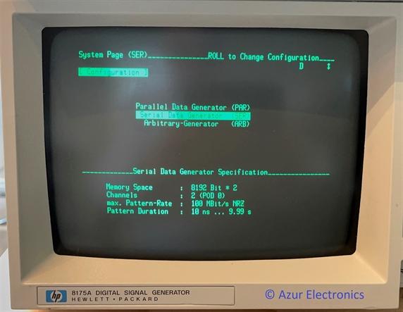
Press the SYSTEM key and move the Cursor down to Serial Data Generator.
Specification is:
Memory Space: 8192 x 2
Channels: 2 (Pod 0)
Max Pattern Rate: 100MBit/s NRZ
Pattern Duration: 10ns to 9.99s
Most of the settings are the same or similar to the settings for the Parallel Data Generator as above. One significant difference is the Data [Format] Menu.
Specification is:
Memory Space: 8192 x 2
Channels: 2 (Pod 0)
Max Pattern Rate: 100MBit/s NRZ
Pattern Duration: 10ns to 9.99s
Most of the settings are the same or similar to the settings for the Parallel Data Generator as above. One significant difference is the Data [Format] Menu.
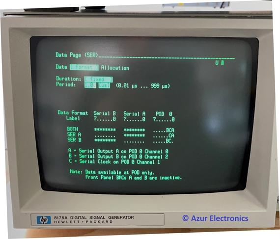
Press DATA key and NEXT to Data[Format] Allocation.
This shows the 2 channels of Pod 0 that can be used.
Pod 0 Channel 0 is Serial A Output.
Pod 0 Channel 1 is Clock Output.
Pod 0 Channel 2 is Serial B Output.
This shows the 2 channels of Pod 0 that can be used.
Pod 0 Channel 0 is Serial A Output.
Pod 0 Channel 1 is Clock Output.
Pod 0 Channel 2 is Serial B Output.
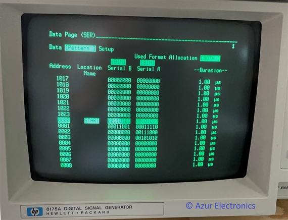
Press DATA key and NEXT to Data[Pattern] Setup.
This allows you to program Pod 0 Channel 0 Serial A Output and Pod 0 Channel 2 Serial B Output.
This allows you to program Pod 0 Channel 0 Serial A Output and Pod 0 Channel 2 Serial B Output.
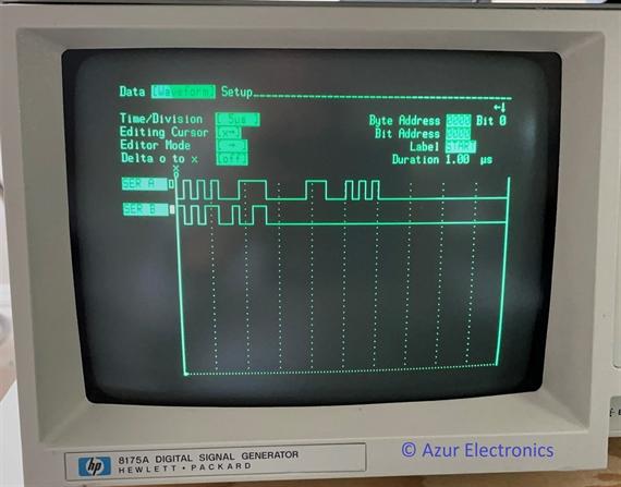
Press DATA key and NEXT to Data[Waveform] Setup.
Alternative method of programming Pod 0 Channel 0 Serial A Output and Pod 0 Channel 2 Serial B Output.
Alternative method of programming Pod 0 Channel 0 Serial A Output and Pod 0 Channel 2 Serial B Output.
For more detailed information: read the Operating and Programming Manual. There is a lot more that the 8175A can do to interact with the 'Device Under Test' and run programs.
ARBITARY GENERATOR
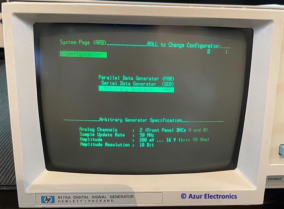
The Arbitary Waveform Generator is even more complex than the Parallel or Serial modes! Operating information is on a separate page, see Operating HP 8175A Arbitary Waveform Generator.
OTHER SECTIONS OF THE OPM & APPENDICES
Parallel Master Slave Operation (p112-113), allows a second 8175A to be connected.
Programming HP-IB (p114-141).
Appendicies:
A - Power-up Detected Error Messages (p142).
B - Operator |Action Related Error Messages (p142-147).
C - Using A Printer (p148-149).
D - Using The Disc Memory Accessory (p150-154).
Read the OPM for more detailed information.
Programming HP-IB (p114-141).
Appendicies:
A - Power-up Detected Error Messages (p142).
B - Operator |Action Related Error Messages (p142-147).
C - Using A Printer (p148-149).
D - Using The Disc Memory Accessory (p150-154).
Read the OPM for more detailed information.