
Welcome to
Azur Electronics
Azur Electronics
ELECTRONICS WORKSHOP
POWER DISTRIBUTION
POWER DISTRIBUTION
Home
Projects
Test Equipment
- Accessories
- Adaptors
- Amplifiers
- Attenuators
- Cables
- Frequency Counters
- Logic Analysers
- Multi-Meters
- Network Analysers
- Oscilloscopes
- Power Meters
- Power Supplies
- Prototyping Equipment
- Signal Generators
- Spectrum Analysers
- Tools
Operating Information
- Operating HP 141T
- Operating HP 1630D
- Operating HP 8175A
- Operating HP 8407A
- Operating HP 8410C
- Operating HP 8552B IF Section
- Operating HP 8553B RF Section
- Operating HP 8554B RF Section
- Operating HP 8555A RF Section
- Operating HP 8556A LF Section
- Operating HP 8594E Spectrum Analyser
- Operating HP 8901B
- Operating LeCroy 9310
Technical
- Allen Key Sizes
- High Voltage Measurement
- HP Cases
- HP Information
- HP-IB Interface Bus
- Measurement Units
- Motorola ECL
- RF Connectors
- RF Power - Voltage Conversion
For Sale
Wanted
Links
About Me
Contact Me
Site Map
All this electronic equipment in my Electronics Workshop requires a lot of 230V ac power sockets. Safety is paramount so all circuits are protected by Circuit Breakers. An early decision was to use UK style 3 pin mains plugs and sockets, so that each circuit was individually fused, usually at 3A.
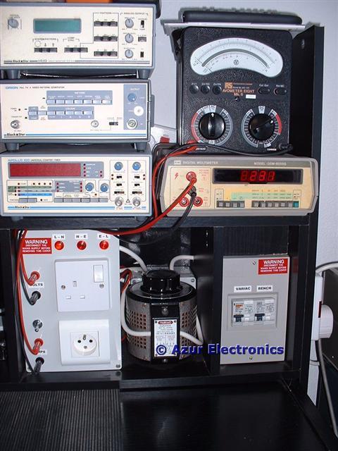
There are 6 parts to the Power Distribution System. 3 of these are at a fixed 230V ac to supply the various items of test equipment, and 3 are variable 0V to 260V ac to supply the Device Under Test (DUT). In this way untested equipment can be slowly powered up while their voltage and current consumption can be monitored for fault conditions.
This is all fairly basic 'electrics', but mains power is dangerous so safety precautions should always be taken to avoid electric shock and to make sure that the equipment is correctly earthed. This is particularly applicable when working on equipment with mains voltages exposed.
This is all fairly basic 'electrics', but mains power is dangerous so safety precautions should always be taken to avoid electric shock and to make sure that the equipment is correctly earthed. This is particularly applicable when working on equipment with mains voltages exposed.
October 2006
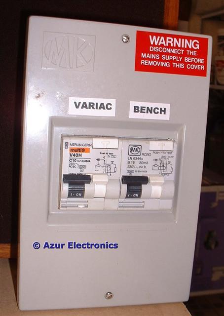
Azur MPS102 Power Control Box
Mains power from a wall socket outlet and 13A fused plug enters the Power Control Box. There are 2 outputs: 1 to supply the Bench test equipment; and 1 to supply the Variac variable voltage supply.
Left: Merlin Gerin RCBO multi 9 V40H C10 30mA trip for Variac supply.
Right: MK RCBO B16 30mA trip for Bench supply RCBO - Residual current Circuit Breaker with Overload protection.
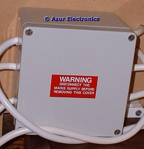
Azur MPS101 Power Junction Box
Mains Power enters from the Power Control Box. There are 5 outputs to Power Distribution Boards. This box is located behind the Variac.
(My first Azur Electronics design!)
Mains Power enters from the Power Control Box. There are 5 outputs to Power Distribution Boards. This box is located behind the Variac.
(My first Azur Electronics design!)
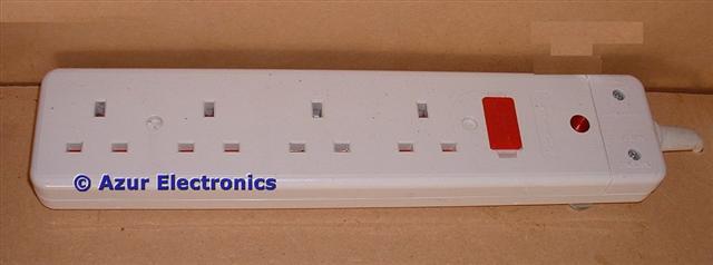
Power Distribution Boards
There are 5 of these in various positions on the Bench and they provide 26 socket outlets. Power enters these directly from the Power Junction Box. Additional power distribution boards are connected to these 5 to provide additional sockets. Only test equipment actually being used is switched on, in order to conserve power and reduce the overall current requirement (slight change, see below).
There are 5 of these in various positions on the Bench and they provide 26 socket outlets. Power enters these directly from the Power Junction Box. Additional power distribution boards are connected to these 5 to provide additional sockets. Only test equipment actually being used is switched on, in order to conserve power and reduce the overall current requirement (slight change, see below).
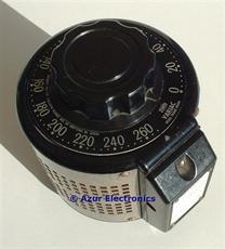
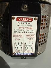
Variac
The Variac is essentially a tapped winding with mains voltage applied to the appropriate tap and the output voltage taken from a variable tap. For a standard 230V ac input voltage, a continuously variable output voltage of between 0V and 260V can be taken. Power enters the Variac from the Power Control Box. The variable output is sent to the Variac Control Box.
The Variac is essentially a tapped winding with mains voltage applied to the appropriate tap and the output voltage taken from a variable tap. For a standard 230V ac input voltage, a continuously variable output voltage of between 0V and 260V can be taken. Power enters the Variac from the Power Control Box. The variable output is sent to the Variac Control Box.
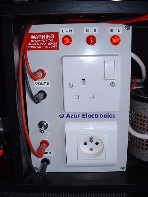
Azur MPS103 Variac Control Box
Variable voltage mains power enters the Variac Control Box from the Variac. This feeds 1 UK Power Socket and 1 European Power Socket to provide power to the Device Under Test (DUT).
3 red neon lamps indicate correct mains wiring: live to neutral, earth to live, but not neutral – earth.
4 off 4mm test sockets are provided to connect a Voltmeter and Ammeter. A bypass switch is provided to short the ammeter terminals together if an ammeter is not connected.
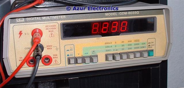
Voltage Monitoring
The output voltage is continuously monitored by a GW Digital Multimeter (DMM) set to the 1,000V ac range.
When testing a "DUT" the initial voltage should always be set to 0V ac on the Variac. A DMM is preferred as absolute values of voltage can be more easily observed. (changed, see below).
The output voltage is continuously monitored by a GW Digital Multimeter (DMM) set to the 1,000V ac range.
When testing a "DUT" the initial voltage should always be set to 0V ac on the Variac. A DMM is preferred as absolute values of voltage can be more easily observed. (changed, see below).
Current Monitoring
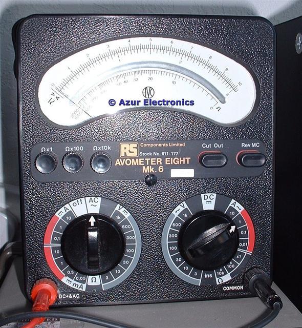
The average (not rms) output current is continuously monitored by an Analogue Multimeter set to the 10A ac range.
When testing a "DUT" the initial current should always be 0A ac (as set by 0V on the Variac). As the voltage is gradually increased, the current should be carefully monitored to provide early indication of a fault condition. The current range can be changed to 1A or 100mA as appropriate.
An analogue multimeter (in this case an AVO 8 Mk 6) is preferred as changes in current can be more easily observed.
November 2011
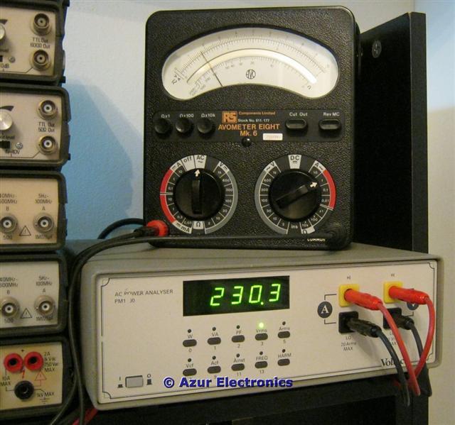
The power monitoring arrangment has been changed by replacing the GW DMM with a Voltech PM100 AC Power Analyser which provides measurements of power, rms voltage & current, frequency, etc. A very useful bit of kit.
The power monitoring arrangment has been changed by replacing the GW DMM with a Voltech PM100 AC Power Analyser which provides measurements of power, rms voltage & current, frequency, etc. A very useful bit of kit.
April 2022
11 years later and this Workshop power distribution is still in regular use. After replacing yet another failed RIFA mains suppression capacitor, I realised that several of these capacitors inside test equipment were powered on whenever the Bench was live.
It is fairly common practice to use a combined mains inlet plug with a filter and often a RIFA mains suppression capacitor connected across the live and neutral before it reaches the test equipment on/off switch.
The solution is to use power distribution boards with individual switched outputs. This way the test equipment can be completely isolated from the mains power.