
Welcome to
Azur Electronics
Azur Electronics
VOLTECH PM1000
AC POWER ANALYSER
AC POWER ANALYSER
Home
Projects
Test Equipment
- Accessories
- Adaptors
- Amplifiers
- Attenuators
- Cables
- Frequency Counters
- Logic Analysers
- Multi-Meters
- Network Analysers
- Oscilloscopes
- Power Meters
- Power Supplies
- Prototyping Equipment
- Signal Generators
- Spectrum Analysers
- Tools
Operating Information
- Operating HP 141T
- Operating HP 1630D
- Operating HP 8175A
- Operating HP 8407A
- Operating HP 8410C
- Operating HP 8552B IF Section
- Operating HP 8553B RF Section
- Operating HP 8554B RF Section
- Operating HP 8555A RF Section
- Operating HP 8556A LF Section
- Operating HP 8594E Spectrum Analyser
- Operating HP 8901B
- Operating LeCroy 9310
Technical
- Allen Key Sizes
- High Voltage Measurement
- HP Cases
- HP Information
- HP-IB Interface Bus
- Measurement Units
- Motorola ECL
- RF Connectors
- RF Power - Voltage Conversion
For Sale
Wanted
Links
About Me
Contact Me
Site Map
The Voltech PM1000 AC Power Analyser was acquired as part of a 'Job Lot'. This is an 8 bit 4MHz Z80 µP based instrument that samples and digitises the voltage and current waveforms to a load then computes the value of the required measurement. Differential input amplifiers allow the 2 inputs to float with respect to each other and to ground. In 1990 the PM1000 cost £nnnn.
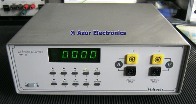
Front view
Front Panel with power on/off switch, voltage input terminals and current input terminals. Plus switches for 10 measurements are available: Power W; Apparent Power VA; Power Factor PF; Voltage Vrms; Current Arms; Voltage Crest Factor Vcf; Current Crest Factor Acf; Instantaneous Peak Current (inrush) Ainst; Frequency FREQ; Harmonic Analysis HARM.
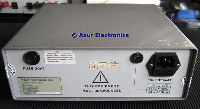
Rear view
Rear Panel with 20A fuse, 110/220 voltage selector switch and CEE22 mains input.
SPECIFICATION
Voltage Input: 2V to 700V rms, 8MΩ input impedance.
Current Input: 20mA to 20A rms, 0.05Ω input impedance.
Frequency Response: dc to 20kHz.
Power Range: 40mW or 40mVA to 14kW or 14kVA.
Power Factor: 0.000 ± 1.000
Voltage Crest Factor: 1.00 to 19.9 (Vpk/Vrms).
Current Crest Factor: 1.00 to 19.9 (Apk / Arms).
Instantaneous Peak Current: 0.1A to 44A pk.
AC Supply Frequency: 5Hz to 20kHz.
Harmonic Analysis: see User Manual p21/22.
November 2011
The User Manual was downloaded (thanks Voltech) and was essential to understand the correct operation of the PM1000. CAUTION: The measured mains voltages and currents can be dangerous!
After removing most of the stickers and cleaning up the unit, the PM1000 appears to be working ok.
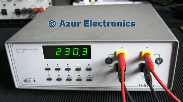
Voltage and Current rms measurements
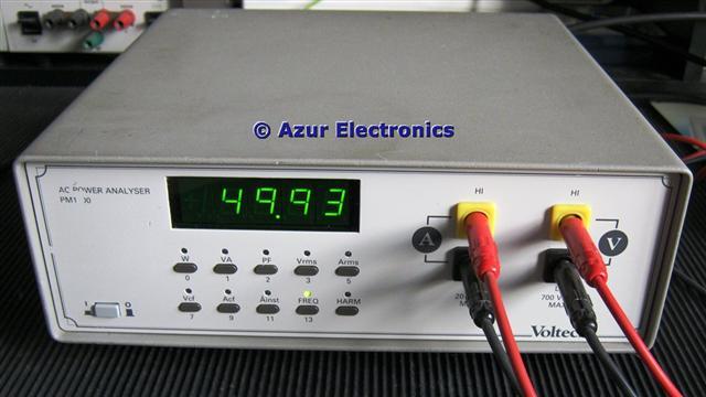
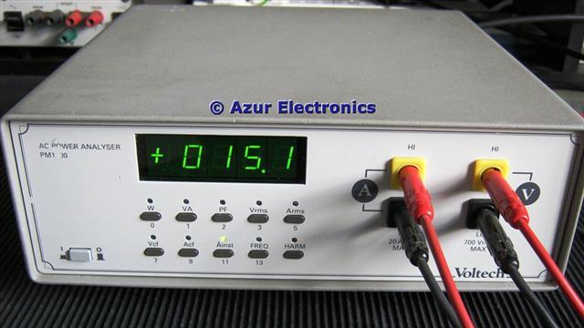
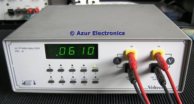
Frequency and Instantaneous Peak Current measurements
Comparing the voltage readings with other meters (an analogue AVO 8 and 2 DMMs) gave fairly consistent readings of 230Vac with the AVO reading low at 224V. However comparing current readings gave different results: with the Voltech and one DMM of 160mA; the AVO and other DMM of 120mA. This appears to be the rms readings in the first case and the average readings in the second case. For a good explanation of the maths see http://www.allaboutcircuits.com/vol_2/chpt_1/3.html.
Quite why this affects current but not voltage measurements needs some further research. [This is because the current waveform is often not a sine wave. In power supplies it is only the peaks of the waveform that are charging up the reservoir capacitors, therefore the true rms value will be very different from the average value.] It just goes to show that you need to be careful what measurement you are making: Vpp, Vp, Vrms, Vav, etc. A quick check is to look at the waveform on an Oscilloscope.
Calibration checks will have to wait until I can find an accurate variable ac source for defined voltages and currents. In the meantime this is a very useful test instrument for the Bench.