
Welcome to
Azur Electronics
Azur Electronics
REPAIR PHILIPS PM 5715
PULSE GENERATOR
PULSE GENERATOR
Home
Projects
Test Equipment
- Accessories
- Adaptors
- Amplifiers
- Attenuators
- Cables
- Frequency Counters
- Logic Analysers
- Multi-Meters
- Network Analysers
- Oscilloscopes
- Power Meters
- Power Supplies
- Prototyping Equipment
- Signal Generators
- Spectrum Analysers
- Tools
Operating Information
- Operating HP 141T
- Operating HP 1630D
- Operating HP 8175A
- Operating HP 8407A
- Operating HP 8410C
- Operating HP 8552B IF Section
- Operating HP 8553B RF Section
- Operating HP 8554B RF Section
- Operating HP 8555A RF Section
- Operating HP 8556A LF Section
- Operating HP 8594E Spectrum Analyser
- Operating HP 8901B
- Operating LeCroy 9310
Technical
- Allen Key Sizes
- High Voltage Measurement
- HP Cases
- HP Information
- HP-IB Interface Bus
- Measurement Units
- Motorola ECL
- RF Connectors
- RF Power - Voltage Conversion
For Sale
Wanted
Links
About Me
Contact Me
Site Map
November 2011
These 2 Philips PM 5715 Pulse Generators were acquired as part of a 'Job Lot' and both described as 'not functioning correctly'. The Instruction Manual and Change Notes were downloaded. Some repair work is required to get these Pulse Generators fully operational.
These 2 Philips PM 5715 Pulse Generators were acquired as part of a 'Job Lot' and both described as 'not functioning correctly'. The Instruction Manual and Change Notes were downloaded. Some repair work is required to get these Pulse Generators fully operational.
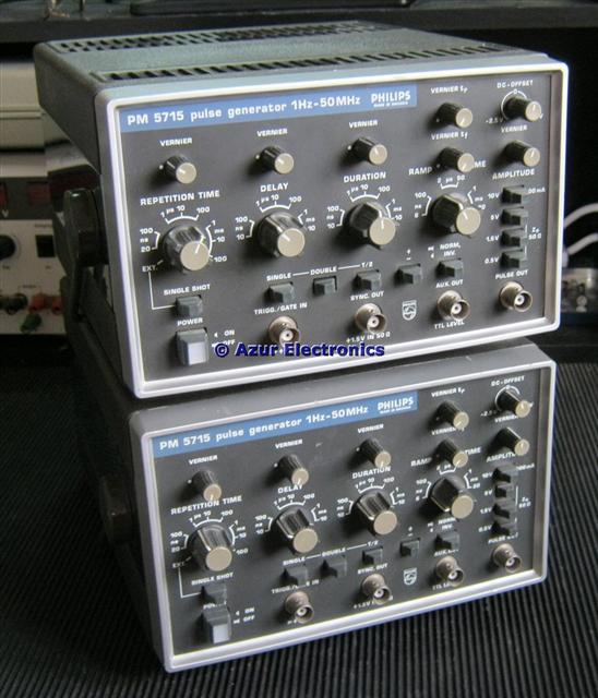
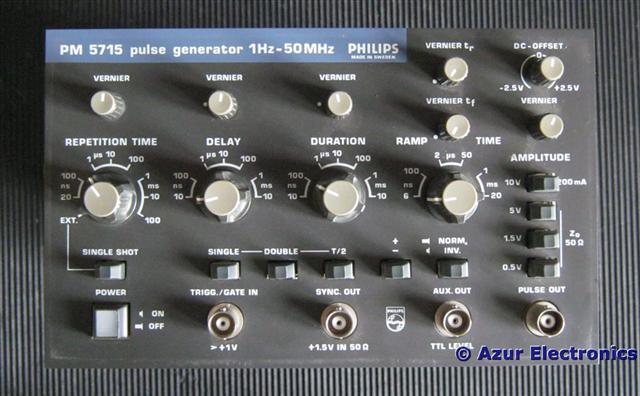
Removed labels and cleaned up exterior. Some minor damage is evident indicating an earlier repair attempt. Removing the case is easy but care must be taken with the front panel surround which is easily damaged.
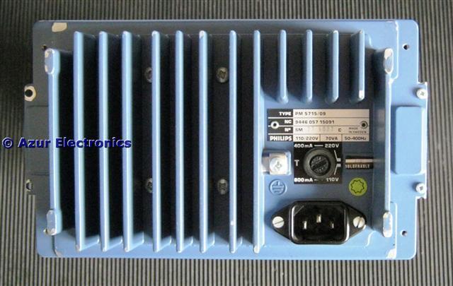
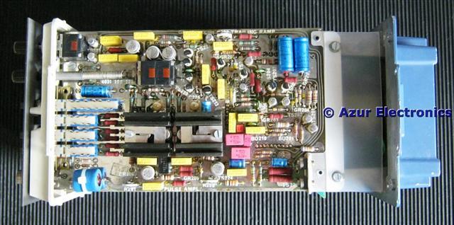
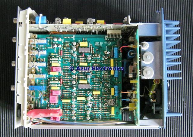
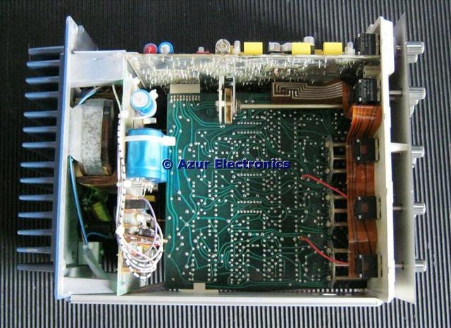
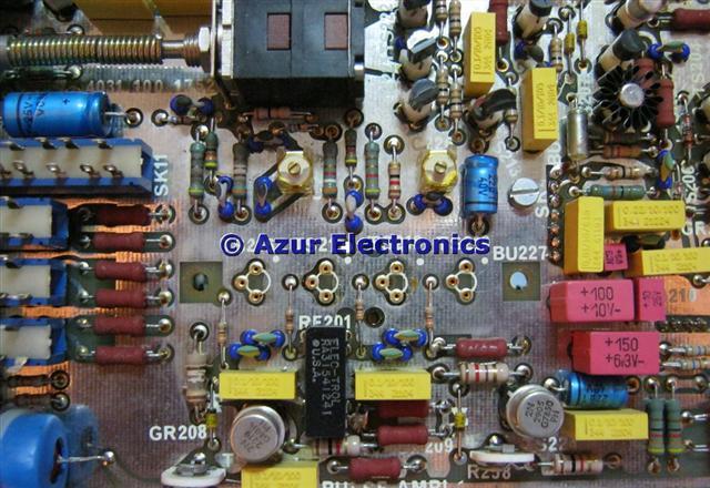
Access to the pcbs for maintenance is good. Caution: there are exposed mains voltages at the rear. Unusually most of the transistors use plug-in bases. Both units are generating pulses with incorrect dc offsets. As the entire circuit is dc coupled, fault finding is not easy!
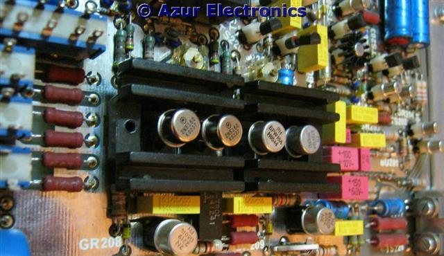
On one unit, there are 4 parallel transistors TS220 to TS223 (PN4258). One of these TS223 was faulty, loading the other 3 transistors to produce incorrect levels.
On one unit, there are 4 parallel transistors TS220 to TS223 (PN4258). One of these TS223 was faulty, loading the other 3 transistors to produce incorrect levels.
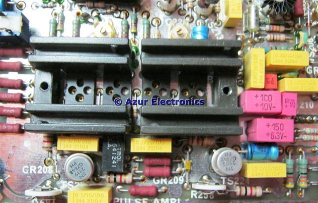
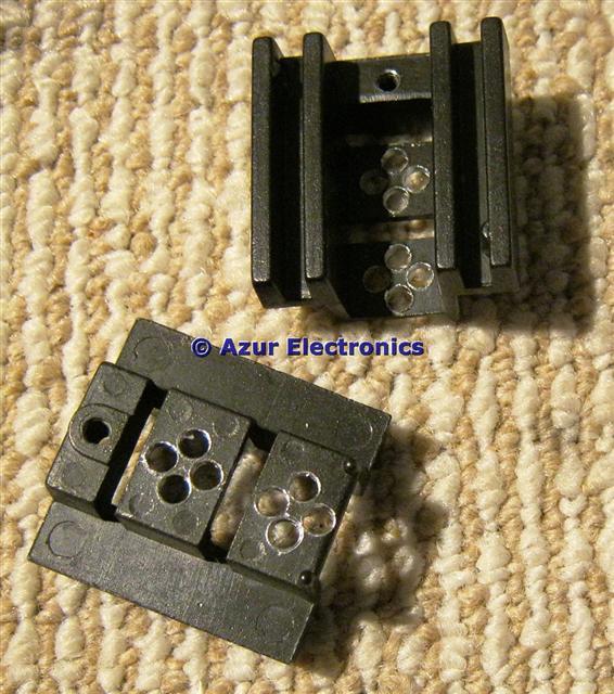
On both units, the parallel output transistors: +ve TS216 & TS217 (2N5160) and -ve TS218 & TS219 (BFW16A) are loading the dc offset levels. These are connected to the Pulse Output BNC without any additional protection so shorting the output to ground could cause damage. Best to replace all of these transistors. Also the heatsinks for these transistors have very small clearance holes for the transistor leads, plus transistor lead sockets on the pcb. The heatsink is at collector voltage. The transistors are all obsolete but eBay has them all: China, UK & USA!
December 2011
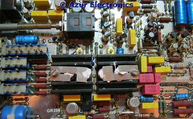
I removed the heatsinks and drilled out the 2.5mm diameter holes +0.1mm at a time to 3mm. Deburr and remove any swarf!
I removed the heatsinks and drilled out the 2.5mm diameter holes +0.1mm at a time to 3mm. Deburr and remove any swarf!
The plug-in transistor lead sockets are very tight so checking them all with a faulty transistor makes sure they all have a good contact. Why not just solder the transistors in?
Replacing the heatsink and the hole clearance is still tight. Previously the transistor leads were cut-down to 5mm which makes them incredibly difficult to fit. Instead I have left them at 13mm approx and sleeved each leg plus a small dab of vaseline to stop the sleeving sliding off. Much easier to fit now.
Fitting M3 x 12mm PAN HD screws and a couple of M4 nuts as washers raises the height of the spring clip. A good blob of heatsink compound will help thermal conductivity.
IMHO this a poor design and should have been modified. If the design engineer had built the first few production units then it probably would have been changed!
IMHO this a poor design and should have been modified. If the design engineer had built the first few production units then it probably would have been changed!
The Pulse Generators are now working again with the correct dc levels and outputs and have both been tested and calibrated.
I suspect that these output transistors may be a common problem with this design as these Pulse Generators are regularly seen on eBay described as 'faulty output'. Even with the heatsink the output pair being used reach 71°C and the other pair are at 40°C. Care must be taken not to short the heatsinks to the pcb earth plane.
I suspect that these output transistors may be a common problem with this design as these Pulse Generators are regularly seen on eBay described as 'faulty output'. Even with the heatsink the output pair being used reach 71°C and the other pair are at 40°C. Care must be taken not to short the heatsinks to the pcb earth plane.