Welcome to
Azur Electronics
Azur Electronics
REPAIR LECROY 9310
DUAL 300MHz OSCILLOSCOPE
DUAL 300MHz OSCILLOSCOPE
Home
Projects
Test Equipment
- Accessories
- Adaptors
- Amplifiers
- Attenuators
- Cables
- Frequency Counters
- Logic Analysers
- Multi-Meters
- Network Analysers
- Oscilloscopes
- Power Meters
- Power Supplies
- Prototyping Equipment
- Signal Generators
- Spectrum Analysers
- Tools
Operating Information
- Operating HP 141T
- Operating HP 1630D
- Operating HP 8175A
- Operating HP 8407A
- Operating HP 8410C
- Operating HP 8552B IF Section
- Operating HP 8553B RF Section
- Operating HP 8554B RF Section
- Operating HP 8555A RF Section
- Operating HP 8556A LF Section
- Operating HP 8594E Spectrum Analyser
- Operating HP 8901B
- Operating LeCroy 9310
Technical
- Allen Key Sizes
- High Voltage Measurement
- HP Cases
- HP Information
- HP-IB Interface Bus
- Measurement Units
- Motorola ECL
- RF Connectors
- RF Power - Voltage Conversion
For Sale
Wanted
Links
About Me
Contact Me
Site Map
October 2011
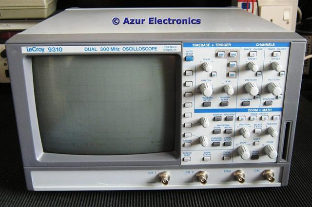
The LeCroy 9310 Dual 300MHz Oscilloscope was acquired as part of a 'Job Lot' and described as 'does not power up'. The Operators Manual, Hands-On Guide (thanks LeCroy) and Service Manual (thanks Tony) were downloaded. Some repair work is required to get this Oscilloscope fully operational. An excellent resource is the forum at LeCroy Owners Group on Yahoo Groups, where other enthusiasts provide advice and encouragement.
Removed labels and cleaned up exterior. Several case screws are missing indicating an earlier unsuccessful repair attempt. Hope I have more luck!
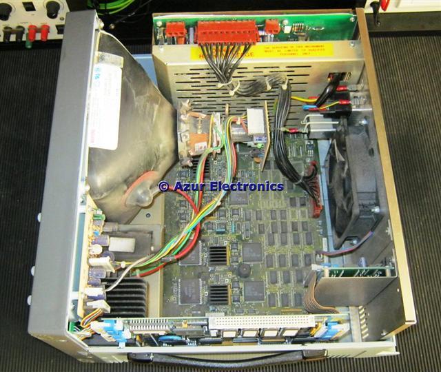
Inside view with cover removed
Removing the top cover shows that the interior is fairly dusty/dirty, so stripping down and cleaning up is the first stage.
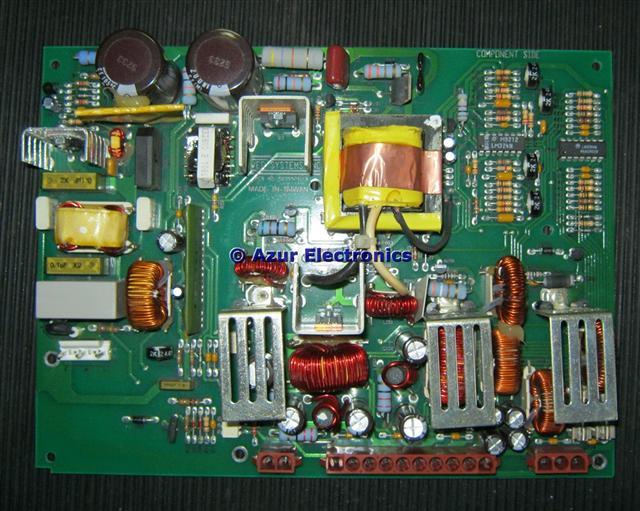
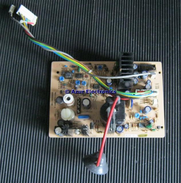
Power Supply pcb
The Power Supply pcb removed from its screens on the LHS of the case. This is not made by LeCroy but by Power Systems Inc of Taiwan. It is a switched mode power supply (SMPS) and luckily there is a circuit diagram in the Service Manual.
Testing the SMPS and although the ac input is ok, there are no dc outputs. CAUTION: these SMPS are dangerous with mains voltages and high currents exposed.
Powered up on a Variac to 115Vac to fault-find. The oscillator transformer primary was not getting any current as R6 47KΩ was open-circuit. This is the power resistor at the top middle of the pcb. Replacing this with a 47KΩ 3W resistor and the dc power rails are now correct at -5.2V, +5.1V, -15V & +15V. This resistor has 290Vdc across it and is dissapating 1.7W and still getting too hot. I have now replaced this with a 5W device to improve reliability. This is a clever but complicated design that will operate at 115V or 230V automatically. Testing at 230Vac produced the same results.
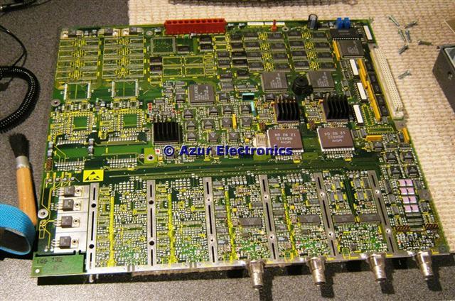
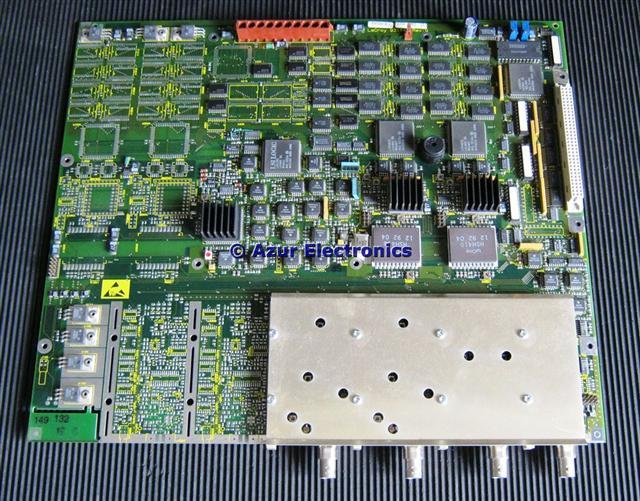
Main Board
The Main Board and its RF screen removed. This large board is not completely populated, so it was probably used in several different Oscilloscope models. The 2 unused input channels can be clearly seen to the front left hand side. With all the LSI chips and SMT parts it would be very difficult to repair this board. Underneath this board was a missing case metal bracket, this could have shorted out lots of pcb tracks if the 9310 had been powered-up!
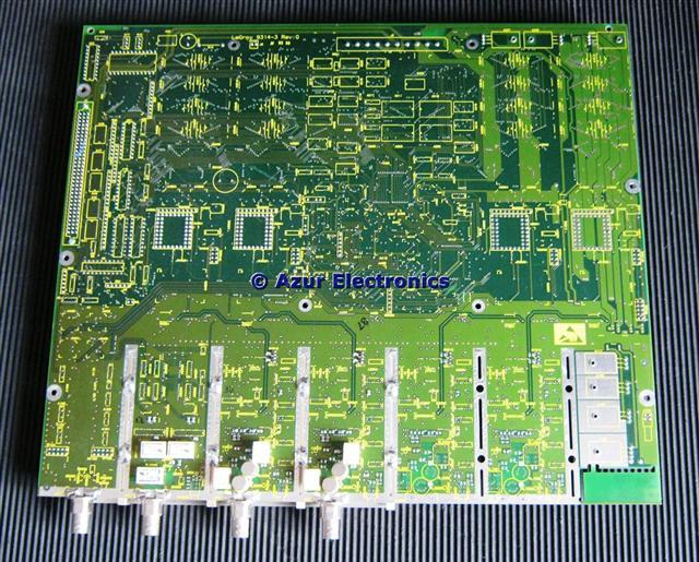
Both sides of the Main Board with RF screen fitted
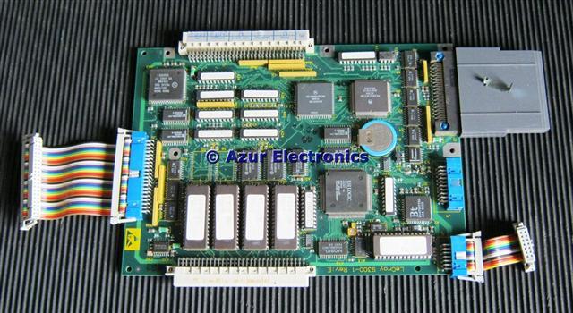
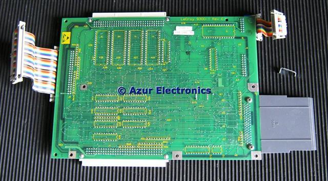
Processor Board, note the small earth lug that fits on to the side case
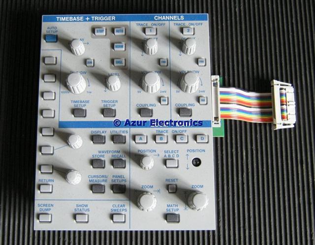
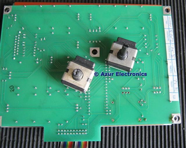
Front Panel controls with a missing 'Position' knob
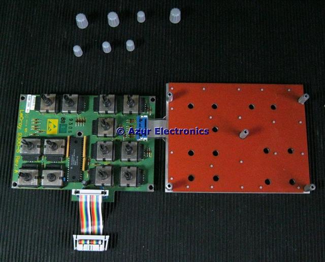
Fairly standard front panel circuit but with a custom LeCroy MFP414 40 pin chip
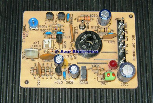
High Voltage Power Supply Board
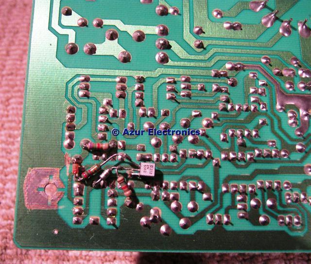
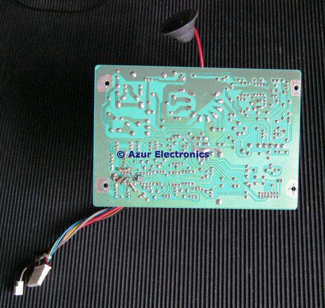
The HVPS is another bought-in assembly from Taiwan.
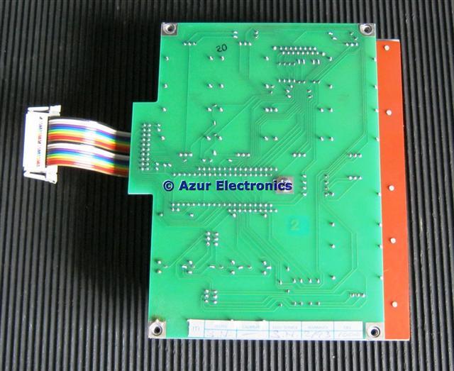
Surprising that a production unit has a
crude modification on the back of the pcb!
Surprising that a production unit has a
crude modification on the back of the pcb!
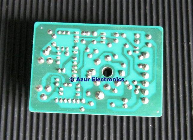
The CRT pcb is also bought-in from Taiwan
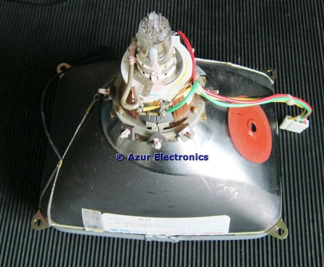
Finally the CRT from Clinton Taiwan Corp. Handle with care!
The screen has slight burning of the image and some minor
scratches but nothing serious that will affect performance
scratches but nothing serious that will affect performance
After cleaning everything up and re-assembly, the Oscilloscope is a bit of a mixture of expensive LeCroy pcb's and cheaper Taiwan parts. The mechanical assemby of the case uses different size, type and length screws. IMHO it could be better designed for reliability and maintainability. One of the case fixing brackets is missing so I will see if I can make a replacement.
Now on to the electronics performance .................
Now on to the electronics performance .................
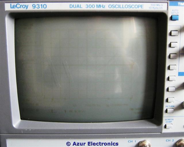
We have a display!
Powered-up on a Variac at 115Vac then 230Vac and we now have a display!
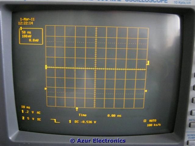
Unfortunately the front panel controls have no effect so there seems to be another fault. The Service Manual describes a 'General Instrument Reset' by simultaneously pressing AUTO SETUP, TOP MENU & RETURN buttons. This does reset the 9310 so the Control Panel is working. The message on the bottom RHS of the screen is now 'STOPPED'.
Checking the RTC Battery on the Processor Board showed only 1.09V, replacing this with a new battery (which is soldered onto the pcb) we have 3.08V and the Oscilloscope is now working again. Running through all the 'Getting Started' checks in the 'Hands On Guide' confirms correct operation of the Oscilloscope.
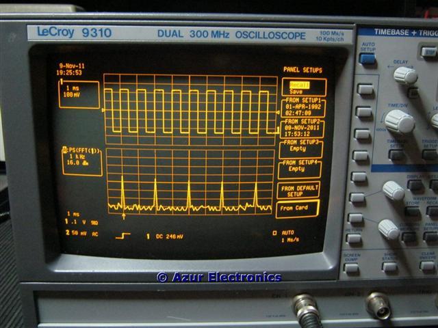
Now working with the correct display
This is a powerful and complicated Oscilloscope which also operates as a Spectrum Analyser. Good to have it working again.
August 2012
Have managed to obtain a RPG (Rotary Position Generator) with the correct small grey knob and a case bracket from another LeCroy Oscilloscope that was being scrapped (thanks Paul). All fitted ok.
The RPG shaft is plastic, so easily broken and therefore a common problem on these oscilloscopes.
Have managed to obtain a RPG (Rotary Position Generator) with the correct small grey knob and a case bracket from another LeCroy Oscilloscope that was being scrapped (thanks Paul). All fitted ok.
The RPG shaft is plastic, so easily broken and therefore a common problem on these oscilloscopes.
The 9310 is now fully operational again
November 2016
Replaced the 3V Battery for the Real Time Clock on the Processor Board.
November 2020
Fails to start-up, this appears to be an intermittant problem with something possibly loading the PSU. The RTC Battery is low and needs replacing again.
Also found a hidden menu option by pressing the 3 4 5 soft keys together. This opens an Internal Menu with options of Calibration Diagnostics; Maintenance; Development sub-menus.
The fault was an optocoupler in the PSU, which is used in a feedback circuit for over-voltage, current and temperature monitoring.