
Welcome to
Azur Electronics
Azur Electronics
REPAIR HP 8620C
SWEEP OSCILLATOR
SWEEP OSCILLATOR
Home
Projects
Test Equipment
- Accessories
- Adaptors
- Amplifiers
- Attenuators
- Cables
- Frequency Counters
- Logic Analysers
- Multi-Meters
- Network Analysers
- Oscilloscopes
- Power Meters
- Power Supplies
- Prototyping Equipment
- Signal Generators
- Spectrum Analysers
- Tools
Operating Information
- Operating HP 141T
- Operating HP 1630D
- Operating HP 8175A
- Operating HP 8407A
- Operating HP 8410C
- Operating HP 8552B IF Section
- Operating HP 8553B RF Section
- Operating HP 8554B RF Section
- Operating HP 8555A RF Section
- Operating HP 8556A LF Section
- Operating HP 8594E Spectrum Analyser
- Operating HP 8901B
- Operating LeCroy 9310
Technical
- Allen Key Sizes
- High Voltage Measurement
- HP Cases
- HP Information
- HP-IB Interface Bus
- Measurement Units
- Motorola ECL
- RF Connectors
- RF Power - Voltage Conversion
For Sale
Wanted
Links
About Me
Contact Me
Site Map
July 2007
The HP 8620C Sweep Oscillator arrived in a bit of a mess but I did buy it described as damaged and not working!
The HP 8620C Sweep Oscillator arrived in a bit of a mess but I did buy it described as damaged and not working!
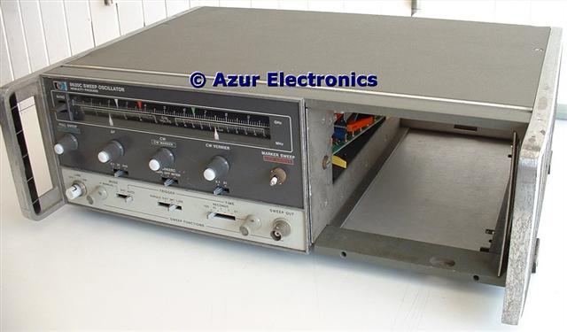
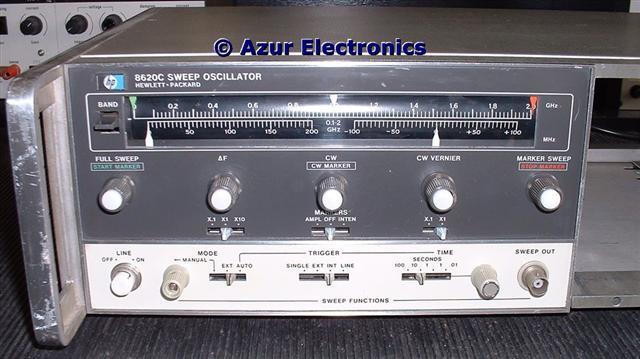
Front view
The case needed a good clean up, the front panel is a bit scratched, one of the knobs was cracked which needed some glue to repair and another knob was missing. The grey knobs each operate a dial mechanism and a variable resistor. The white centre knobs act as a pushbuttons, through the centre of the variable resistors; and are translucent for the display lamps, which are also wired through the centre of the variable resistors! This complicated feature is unique in all my test equipment.
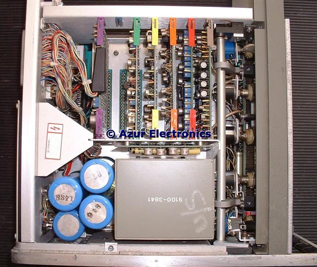
Top view with covers removed
On removing the top cover, all the plug-in pcb's were loose inside the case (as can be seen in the top photo) and someone had written "U/S" on top of the mains power transformer. Not a good sign, so I decided to completely strip down the Sweeper to Assembly level.
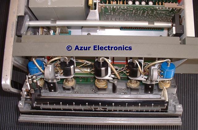
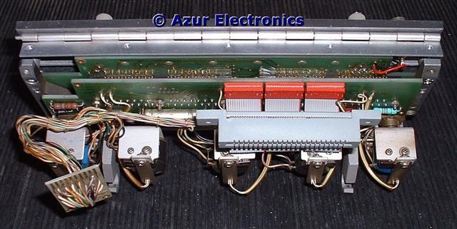
Front panel hinged down
The front panel can be hinged down by operating a lever in the RF Plug-In compartment. The Scale was also loose and needed refitting. Up to 4 Scales can be fitted, different Scales are required for each RF Plug-In to indicate frequency, although I only have 1 Scale. This is 0 to 10 for Cal Volts.
The 8620C is fairly easy to strip down, although lots of notes and photos are required to aid re-assembly. The mains power transformer is sealed inside a metal box but the 5 secondary windings go to a 10 way plug, so the transformer can be tested in isolation and was ok. Connecting the transformer to the motherboard and the A8 Rectifier Assembly showed the dc voltages were wrong and 3 rectifier diodes needed replacing. Refitting the 6 plug-in PCB's revealed 2 further faults which were due to wires being trapped and shorting out. Positioning of the rear panel is fairly critical as the dense wiring can easily become trapped or foul the fan on re-assembly. The mains wiring is not fully insulated!
Testing the Sweeper with the HP 86220A RF Plug-In and everything appears to be working. Not all the Operator's Checks were completed as a HP 8470A Crystal Detector 10MHz to 18GHz is required. Operator's Checks and Performance Tests will be carried out when a Crystal Detector is available.
February 2010
Fitted 2 replacement knobs and white centre push-buttons from a scrap 8620A. Now all the push-buttons are correct.
Fitted 2 replacement knobs and white centre push-buttons from a scrap 8620A. Now all the push-buttons are correct.
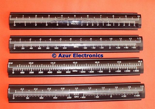
Fitted 2 more scales: one for 0 to 1.3GHz for the 86220A and one for 12 to 18GHz for the 86260A RF Plug-In's.
There must be a lot of different scales in the complete set and there are also differences between the A, B & C versions.
There must be a lot of different scales in the complete set and there are also differences between the A, B & C versions.
The 'Markers' were not working. Substituting the A1 PCB 08620-60111 from the 2nd 8620C solved this problem. It looks if the U7 IC, an obsolete MC817P, had failed, this needs testing. On the replacement pcb this IC had already been changed for a 7402 which has a completely different pin-out, therefore lots of cut tracks and wire links on the back!
Testing the MC817P on a prototype board showed that one of the Quad NOR gates had failed, luckily the 4th gate was not used so with a few pcb cut-tracks and wire-links the gates were swopped over. Refitted the A1 PCB and the 'Markers' are now working again. The MC817P is an obsolete Motorola RTL (Resistor Transistor Logic) IC and although spares were available, it is a much better solution to change this to 74 series TTL although more modifications are required. This may be a common problem on the 8620C and it is a bit strange why HP mixed RTL and TTL on this pcb.
Now that I have a HP 8471A RF Detector, all the Operator's Checks and Performance Tests have at last been completed satisfactorily.
March 2010
The 2nd 8620C also needs some repair work. After a good clean up and replacing some control knobs from a scrap 8620A, the Sweep Oscillator is in a fairly good cosmetic condition.
Testing the MC817P on a prototype board showed that one of the Quad NOR gates had failed, luckily the 4th gate was not used so with a few pcb cut-tracks and wire-links the gates were swopped over. Refitted the A1 PCB and the 'Markers' are now working again. The MC817P is an obsolete Motorola RTL (Resistor Transistor Logic) IC and although spares were available, it is a much better solution to change this to 74 series TTL although more modifications are required. This may be a common problem on the 8620C and it is a bit strange why HP mixed RTL and TTL on this pcb.
Now that I have a HP 8471A RF Detector, all the Operator's Checks and Performance Tests have at last been completed satisfactorily.
March 2010
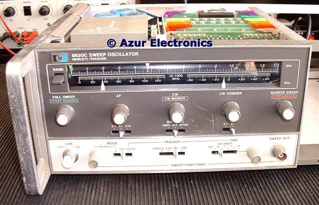
The 2nd 8620C also needs some repair work. After a good clean up and replacing some control knobs from a scrap 8620A, the Sweep Oscillator is in a fairly good cosmetic condition.
Front view of 2nd 8620C
Carrying out the Operator's Checks shows that the Sweep Output is intermittant, the Manual Mode control does not work and the Amplitude Markers are missing although the Intensity Markers are ok.
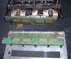
Front panel assembly
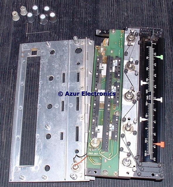
Carefully stripping down this very complicated Front Panel assembly revealed that a spring was missing in the Mode switch which was causing a bad contact.
Unsoldering the Manual variable resistor provides access to the switch contacts and a replacement spring from a scrap 8620A was fitted. All the switch contacts were cleaned as were the gold mating contacts between the 2 pcb's.
These switches are not very robust so some some care is required!
Unsoldering the Manual variable resistor provides access to the switch contacts and a replacement spring from a scrap 8620A was fitted. All the switch contacts were cleaned as were the gold mating contacts between the 2 pcb's.
These switches are not very robust so some some care is required!
The missing 'Amplitude Markers' were traced to a fault in the (not tested yet) HP 86222A RF Plug-In loading the signal. Replacing this with a 86220A solved the problem. TP10 on the A1 pcb should show the 3 marker conditions, AMPL-OFF-INTEN correctly. Note that the Sweep Out only shows OFF -INTEN but not AMPL.
The Operator's Checks and Performance Tests were now completed satisfactorily.
January 2011
The CW pointer belt on my 2nd 8620C had snapped and on inspection the CW Vernier was frayed. My scrap 8620A had a spare CW Vernier belt to swop over but I had already used the CW belt. The Full Sweep belt was much too long but the Marker Sweep belt was just a bit too long.
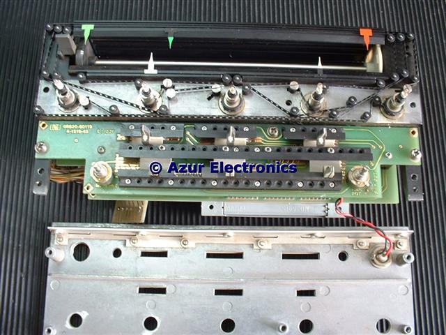
Modified assembly
The solution was to drill an extra hole in the chassis and fit an additional guide wheel and roller (spot which one) to take up the slack. A very fiddly, time consuming job requiring dexterity and good eyesight - a tad limited in my case!
Next time these fragile fabric sprocket belts break and I'm in trouble, so looking for an alternative solution. Apparently 8mm film can be used instead!
Next time these fragile fabric sprocket belts break and I'm in trouble, so looking for an alternative solution. Apparently 8mm film can be used instead!