
Welcome to
Azur Electronics
Azur Electronics
REPAIR HP 8016A
WORD GENERATOR
WORD GENERATOR
Home
Projects
Test Equipment
- Accessories
- Adaptors
- Amplifiers
- Attenuators
- Cables
- Frequency Counters
- Logic Analysers
- Multi-Meters
- Network Analysers
- Oscilloscopes
- Power Meters
- Power Supplies
- Prototyping Equipment
- Signal Generators
- Spectrum Analysers
- Tools
Operating Information
- Operating HP 141T
- Operating HP 1630D
- Operating HP 8175A
- Operating HP 8407A
- Operating HP 8410C
- Operating HP 8552B IF Section
- Operating HP 8553B RF Section
- Operating HP 8554B RF Section
- Operating HP 8555A RF Section
- Operating HP 8556A LF Section
- Operating HP 8594E Spectrum Analyser
- Operating HP 8901B
- Operating LeCroy 9310
Technical
- Allen Key Sizes
- High Voltage Measurement
- HP Cases
- HP Information
- HP-IB Interface Bus
- Measurement Units
- Motorola ECL
- RF Connectors
- RF Power - Voltage Conversion
For Sale
Wanted
Links
About Me
Contact Me
Site Map
September 2008
The HP 8016A Word Generator is a complex item of test equipment with lots of inter-connecting coaxial & ribbon cables in between the pcb's and to the front panel.
The HP 8016A Word Generator is a complex item of test equipment with lots of inter-connecting coaxial & ribbon cables in between the pcb's and to the front panel.
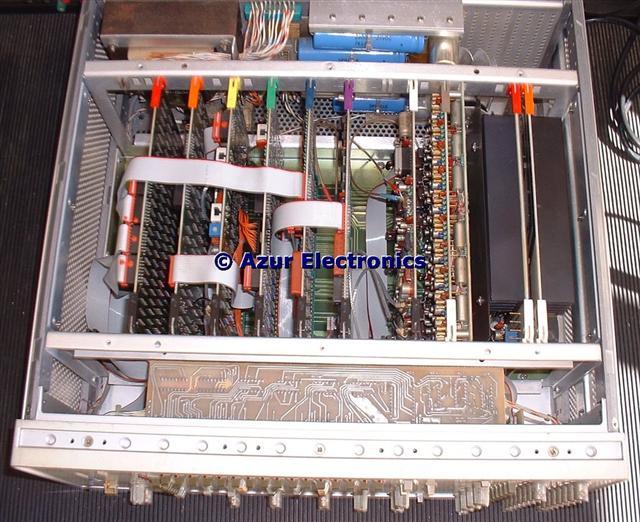
Top view with cover removed
Removing the covers revealed a lot of dust inside so a complete strip down to 'Assembly' level was required.
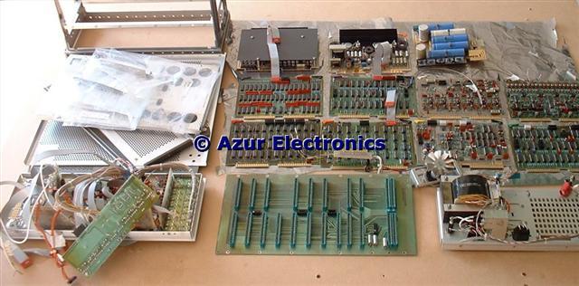
Kit of Parts!
The 8016A stripped down for cleaning and inspecting. Easy to dismantle although notes and photos required to identify where everything fits. Only 2 wires (for front panel power LED) needed cutting to dismantle.
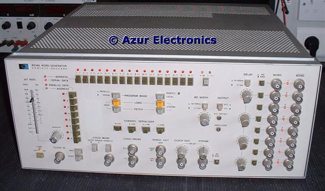
Reassembled Front view
All cleaned up and reassembled. Everything appears to be working, power rails are correct and all the LEDs light. More detailed testing has revealed the following problems:
Of the 8 LED's associated with the WORD outputs, LED's 1 to 7 were intermittant. This was traced to a connector behind the front panel making poor contact. The LED's are controlled by the CHANNEL SERIALIZER push buttons. 8 x 32 lights all the LED's; 4 x 64 lights LED's 2, 4, 6 & 8; 2 x 128 lights LED's 4 & 8; and 1 x 256 lights LED 8.
The BIT RATE slider switch produces the correct outputs at CLOCK OUT except for the external clock input. This appears to be a fault in the A5 Bit Rate PCB.
On power-up, row LED 8 & column LED 4 are off, pushing the appropriate switch turns them on. Also the bit pattern varies between outputs with bits 1 to 16 addressable, but bits 17 to 32 are not controllable. None of the bits on the strobe output are controllable.
Without the full Operating & Service Manual it is very difficult to analyse the circuits and troubleshoot the faults. Despite this, many of the functions do work and the 8016A is a very versatile pulse generator. For instance, the 8016A can generate a 10μs positive going pulse width with a 1s period, which is required to test the 5004A. A negative going pulse was produced by feeding this output to the external clock input of the 3762A and using its inverted CLOCK output. Maybe unconventional but very useful, especially the various pulse width and delay functions. Once the bit rate patterns can be correctly controlled, other test signals can be generated.
January 2009
I have now bought the full Manual from Artek, so repair work will proceed as soon as I have time.
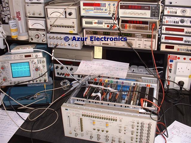
June/July 2009
Started work on testing the Generator. Although the Manual provides circuit descriptions, diagrams and test point waveforms (as usual with HP equipment), the circuitry is surprisingly complex with both TTL and ECL.
Of the 8 LED's associated with the WORD outputs, LED's 1 to 7 were intermittant. This was traced to a connector behind the front panel making poor contact. The LED's are controlled by the CHANNEL SERIALIZER push buttons. 8 x 32 lights all the LED's; 4 x 64 lights LED's 2, 4, 6 & 8; 2 x 128 lights LED's 4 & 8; and 1 x 256 lights LED 8.
The BIT RATE slider switch produces the correct outputs at CLOCK OUT except for the external clock input. This appears to be a fault in the A5 Bit Rate PCB.
On power-up, row LED 8 & column LED 4 are off, pushing the appropriate switch turns them on. Also the bit pattern varies between outputs with bits 1 to 16 addressable, but bits 17 to 32 are not controllable. None of the bits on the strobe output are controllable.
Without the full Operating & Service Manual it is very difficult to analyse the circuits and troubleshoot the faults. Despite this, many of the functions do work and the 8016A is a very versatile pulse generator. For instance, the 8016A can generate a 10μs positive going pulse width with a 1s period, which is required to test the 5004A. A negative going pulse was produced by feeding this output to the external clock input of the 3762A and using its inverted CLOCK output. Maybe unconventional but very useful, especially the various pulse width and delay functions. Once the bit rate patterns can be correctly controlled, other test signals can be generated.
January 2009
I have now bought the full Manual from Artek, so repair work will proceed as soon as I have time.
June/July 2009
Started work on testing the Generator. Although the Manual provides circuit descriptions, diagrams and test point waveforms (as usual with HP equipment), the circuitry is surprisingly complex with both TTL and ECL.
Another complication is that detailed information is only provided in the Manual for trouble-shooting the analogue boards (A5, A10, A11, A12,A25 & A26).
Faulty digital boards (A2, A3, A4, A6, A7 & A8) were intended to be discarded and then replacements obtained from HP, so only limited circuit and parts list information is provided in the Manual.
Faulty digital boards (A2, A3, A4, A6, A7 & A8) were intended to be discarded and then replacements obtained from HP, so only limited circuit and parts list information is provided in the Manual.
Access to the PCB's is made more difficult because of all the inter-connecting coax and ribbon cables, this precludes the use of extender cards, which I don't have! My solution, as usual, is to solder wire links to the pcb so that I can examine various points of the circuitry. The main inputs and outputs to each board can be examined on the edge connectors underneath the motherboard.
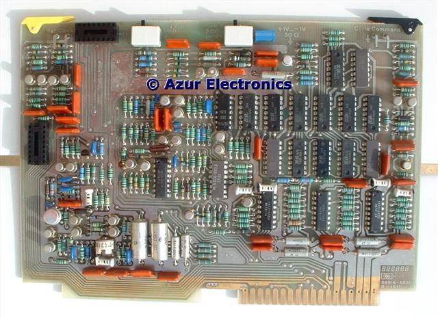
The Bit Rate Board A5 includes a 50MHz ramp generator, a divider chain for 5MHz down to 0.5Hz, an external clock input, auto/single cycle control, synchronisation, plus TTL/ECL conversion all of which were tested.
The fault with the external clock input was traced to transistor Q16 which was swapped with Q17 to maintain the high frequency performance and the less important Q17 was replaced with a BC327 PNP transistor. Q16 had probably been subject to an input overload.
The fault with the external clock input was traced to transistor Q16 which was swapped with Q17 to maintain the high frequency performance and the less important Q17 was replaced with a BC327 PNP transistor. Q16 had probably been subject to an input overload.
Started 'Performance Checks' and Bit Rate now ok, but Load Data / Fetch Data and Column Number Display both give some errors. Assemblies A14 Row Data Switch and A15 Column Data Switch both appear to be ok as although not all LEDs are lit on power-up, they can all be switched on/off ok.
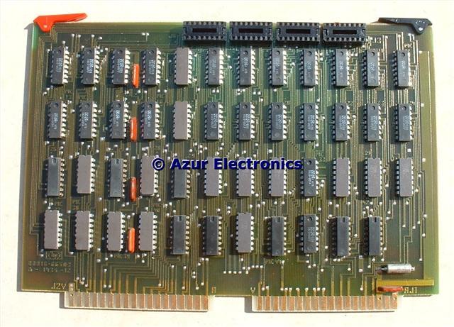
The Buffer Register Board A3 can be accessed through the left hand side panel of the chassis. This allows the use of IC test clips (much easier than soldering wire links). This appears to be working ok. It may be that the clock signals from A4 Control Board are not initialising the flip-flops and latches properly.
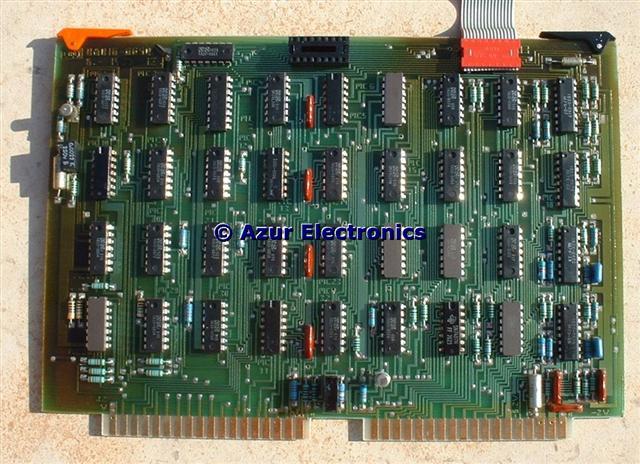
The Control Board A4 has several outputs which are not being clocked. 2 IC's appear to be faulty (U18 MC1039P & U30 SN7410N) and are awaiting replacements.
This raises another issue. The MC1039P is a Motorola ECL (or MECL) IC which is now obsolete. There is not much information or data sheets available on the web. Some research is therefore necessary, see Motorola ECL for details.
This raises another issue. The MC1039P is a Motorola ECL (or MECL) IC which is now obsolete. There is not much information or data sheets available on the web. Some research is therefore necessary, see Motorola ECL for details.
Checking the inputs and outputs for Address Counter Board A6 has not shown any significant issues.
Just about to test the truth table for the counter and a new problem with the bit rate from A5 has arisen! Snakes & Ladders - frustrating, mainly because of lack of extender cards for intensive fault finding, especially when logic chains have feedback loops.
Just about to test the truth table for the counter and a new problem with the bit rate from A5 has arisen! Snakes & Ladders - frustrating, mainly because of lack of extender cards for intensive fault finding, especially when logic chains have feedback loops.
August 2009
After a few days of fault-finding on A5, it turns out that the fault is an incorrect input from A6 which is disabling the clock dividers. At least I know how A5 works in some detail now!
Sourcing obsolete parts such as the 1970's Motorola MC1039P is not easy. It would probably be easier and in the long run probably cheaper as well, to buy a second HP 8016A for use as spares unit.
October 2009
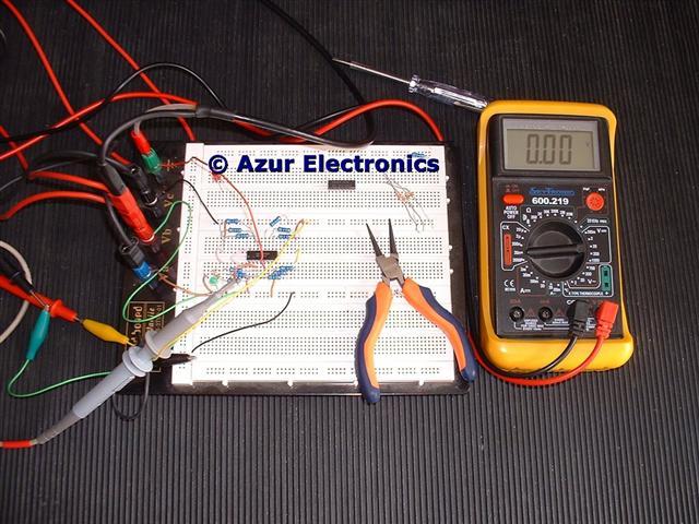
Removed 2 ICs on Control Board A4 and fitted IC Sockets in their place. Testing the ICs on a prototype breadboard revealed that U30 SN7410N did in fact have one faulty NAND gate that was not switching. Replacing this IC with a SN74LS10N means that the Load Strobe / Fetch Strobe is now working.
Testing the IC U18 MC1039P was more difficult as this is an ECL to TTL logic converter. DC power supplies of +5V, 0V & -5.2V are required. I used the HP 3762A to generate an ECL input signal of -0.75V to -1.5V but this did not switch the IC correctly as the output stayed at a TTL logic high. The bit rate was too fast with a 20nS pulse. Using the HP 8018A clock output to drive the 3762A external clock input solved the problem and produced a 150nS pulse. Amazing how versatile these Generators are even if I am using them in a very non-standard way. The IC tested ok and had a very similar performance to some replacement ICs that I had sourced with some difficulty from eBay USA. So I have some spare MC1039P's if anyone needs them.
I will keep a look out for another 8016A as a source of spares and maybe replacement boards as a faster solution.
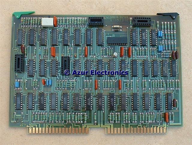
Further work on the A6 Address Counter Board has shown it is a multi-layer pcb which makes removing ICs much more difficult (see Tools for my technique). The HGACL output signal is being loaded by another IC on the pcb, problem is it could be any one of 5 ICs. Also following the logic design is proving very confusing, partly because of all the complex feedback paths.
So far: IC U28 MC10102P has been proved to be faulty and replaced with an IC Socket and spare pre-tested IC. Removing U37 then U31 both MC10106P (for which I don't have any spares) has found the short. Continuity testing each hole to all its destinations on the pcb plus insulation between holes before and after fitting an IC Socket is laborious but does increase confidence in the pcb and circuit diagram.
After a few days of fault-finding on A5, it turns out that the fault is an incorrect input from A6 which is disabling the clock dividers. At least I know how A5 works in some detail now!
Sourcing obsolete parts such as the 1970's Motorola MC1039P is not easy. It would probably be easier and in the long run probably cheaper as well, to buy a second HP 8016A for use as spares unit.
October 2009
Removed 2 ICs on Control Board A4 and fitted IC Sockets in their place. Testing the ICs on a prototype breadboard revealed that U30 SN7410N did in fact have one faulty NAND gate that was not switching. Replacing this IC with a SN74LS10N means that the Load Strobe / Fetch Strobe is now working.
Testing the IC U18 MC1039P was more difficult as this is an ECL to TTL logic converter. DC power supplies of +5V, 0V & -5.2V are required. I used the HP 3762A to generate an ECL input signal of -0.75V to -1.5V but this did not switch the IC correctly as the output stayed at a TTL logic high. The bit rate was too fast with a 20nS pulse. Using the HP 8018A clock output to drive the 3762A external clock input solved the problem and produced a 150nS pulse. Amazing how versatile these Generators are even if I am using them in a very non-standard way. The IC tested ok and had a very similar performance to some replacement ICs that I had sourced with some difficulty from eBay USA. So I have some spare MC1039P's if anyone needs them.
I will keep a look out for another 8016A as a source of spares and maybe replacement boards as a faster solution.
Further work on the A6 Address Counter Board has shown it is a multi-layer pcb which makes removing ICs much more difficult (see Tools for my technique). The HGACL output signal is being loaded by another IC on the pcb, problem is it could be any one of 5 ICs. Also following the logic design is proving very confusing, partly because of all the complex feedback paths.
So far: IC U28 MC10102P has been proved to be faulty and replaced with an IC Socket and spare pre-tested IC. Removing U37 then U31 both MC10106P (for which I don't have any spares) has found the short. Continuity testing each hole to all its destinations on the pcb plus insulation between holes before and after fitting an IC Socket is laborious but does increase confidence in the pcb and circuit diagram.
November 2009
Testing the removed ICs on a prototype breadboard shows that U37 is ok and U31 had failed with excessive current consumption at -5.2V @ 140mA instead of the normal 18mA. The HGACL output on pin 2 was shorting to pin 1 Vcc1 0V rail and none of the gates were switching with an ECL input. Need to source some replacement MC10106 ICs.
Bought 2 x MC10106 on eBay UK. Tested on breadboard ok and fitted to A6. The HGACL signal is now ok. All 32 data bits are now addressible.
April 2010
This is an incredibly complex design and without detailed circuit descriptions for the digital boards, it is very difficult to repair. I have decided that this is taking too much of my time and holding up more important projects. This is the first project that I have admitted (temporary) defeat on! Most of the functions are now working satisfactorily and I can use the Generator to provide complex pulse waveforms. Frustrating but pragmatic. Maybe one day .......
This is an incredibly complex design and without detailed circuit descriptions for the digital boards, it is very difficult to repair. I have decided that this is taking too much of my time and holding up more important projects. This is the first project that I have admitted (temporary) defeat on! Most of the functions are now working satisfactorily and I can use the Generator to provide complex pulse waveforms. Frustrating but pragmatic. Maybe one day .......