
Welcome to
Azur Electronics
Azur Electronics
REPAIR HP 5342A MICROWAVE
FREQUENCY COUNTER
FREQUENCY COUNTER
Home
Projects
Test Equipment
- Accessories
- Adaptors
- Amplifiers
- Attenuators
- Cables
- Frequency Counters
- Logic Analysers
- Multi-Meters
- Network Analysers
- Oscilloscopes
- Power Meters
- Power Supplies
- Prototyping Equipment
- Signal Generators
- Spectrum Analysers
- Tools
Operating Information
- Operating HP 141T
- Operating HP 1630D
- Operating HP 8175A
- Operating HP 8407A
- Operating HP 8410C
- Operating HP 8552B IF Section
- Operating HP 8553B RF Section
- Operating HP 8554B RF Section
- Operating HP 8555A RF Section
- Operating HP 8556A LF Section
- Operating HP 8594E Spectrum Analyser
- Operating HP 8901B
- Operating LeCroy 9310
Technical
- Allen Key Sizes
- High Voltage Measurement
- HP Cases
- HP Information
- HP-IB Interface Bus
- Measurement Units
- Motorola ECL
- RF Connectors
- RF Power - Voltage Conversion
For Sale
Wanted
Links
About Me
Contact Me
Site Map
May 2008
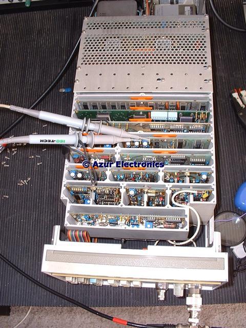
This had a really annoying fault that was probably there when I bought the Counter. It worked fine in the low frequency range 10Hz to 520MHz. However, in the high frequency range 500MHz to 24GHz it would not work in Automatic mode. If you knew the approximate frequency to be measured, to the nearest 50MHz, you could set this up in Manual mode and it would provide the correct frequency.
Just to complicate matters, I didn't have any of the extender cards, so it was difficult to troubleshoot on the pcb's in their RF shielded boxes. I used short wire links soldered to the pcb. Not ideal but as long as you don't solder to the gold edge connector finger it works!
CAUTION: This Counter uses a "switching" power supply so there are high voltages on the Motherboard and power supply pcb's.
One advantage of a fault is that it forces you to understand how these counters work in some detail, especially the down-conversion techniques used to extend the frequency range past 500MHz. Recommended reading is HP Application Note 200-1 "Fundamentals of Microwave Frequency Counters".
One advantage of a fault is that it forces you to understand how these counters work in some detail, especially the down-conversion techniques used to extend the frequency range past 500MHz. Recommended reading is HP Application Note 200-1 "Fundamentals of Microwave Frequency Counters".
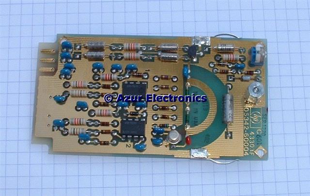
The actual fault turned out to be a failed IC, U1 on the A4 Offset Voltage Controlled Oscillator. I found another source of this particular signal and linked it across to provide the required output signal at 300MHz to 350MHz. The 8 pin IC is a HP special, part no 1826-0372 5GHz Limiter/Amplifier.
(See change below).
(See change below).
December 2008
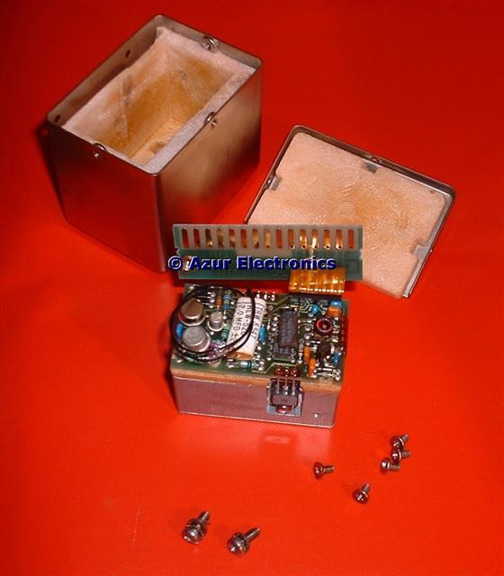
Some further work on comparing this Frequency Counter with others and investigating using it as a locking source, indicated that the 10MHz frequency standard output was some 100Hz low. Some earlier notes showed that the 'OVN' LED on the front panel was not working either. On checking the temperature controlled crystal oscillator [HP 10811-60111] it was cold! Stripping it down revealed no obvious faults. With help from the HP Forum (thanks Dan and others) suggested that the Thermal Fuse was probably blown. This is the device above the 8 pin IC. This turned out to be the problem.
Some further work on comparing this Frequency Counter with others and investigating using it as a locking source, indicated that the 10MHz frequency standard output was some 100Hz low. Some earlier notes showed that the 'OVN' LED on the front panel was not working either. On checking the temperature controlled crystal oscillator [HP 10811-60111] it was cold! Stripping it down revealed no obvious faults. With help from the HP Forum (thanks Dan and others) suggested that the Thermal Fuse was probably blown. This is the device above the 8 pin IC. This turned out to be the problem.
The solution suggested was to short it out. Initially the heater takes about 400mA of current for about 5 minutes to warm-up. During this time the front panel 'OVN' LED is on. When warmed-up the LED goes out and the current drops to about 100mA. Note that the Oscillator is still powered when in 'Standby' mode.
As I only use the 5342A for a few hours at a time, the Thermal Fuse is not essential and I can monitor that the front panel 'OVN' LED does turn off.
As I only use the 5342A for a few hours at a time, the Thermal Fuse is not essential and I can monitor that the front panel 'OVN' LED does turn off.
Downloaded the Manual (nearly 100 pages) just for the Oscillator and it is a complicated little beast! Now working correctly and adjusted to 10,000,000Hz.
January 2015
Started repair work on a second 5342A which is a slightly earlier serial number. This measures frequency on both ranges and has the amplitude measurement option 002. After a clean up and checking all the pcb's it has a fault with the keypad 0 to 9 not working. This turned out to be a poor contact between the A1 & A2 PCBs. This uses gold pads on the PCBs with an inter-connector between them. It is essential that the 2 fixing screws and nuts are tight to avoid intermittant contacts. Checked out the operation of the Counter and all ok.
December 2015
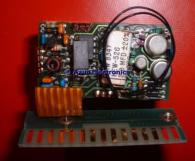
Started repair work on a third 5342A which has an even earlier serial number. This occasionally blows the mains fuse. The wiring from the voltage selector to the motherboard had loose contacts, easy to fix. The A19 Power Supply (Line) has an input circuit to the SMPS using thermistors and varistors to limit the inrush current and protect against voltage transients. These components had burn marks so were replaced.
Not counting on the 500MHz to 18GHz range, possibly A26 Sampler Driver. The front panel variable resistor is either short-circuit or open-circuit so not gating properly. This needs replacing.
Also swopped over 2 PCBs A4 & A6 with first 5342A. New parts required for these as well. In the Operating and Service Manual a lot of the parts have only HP part numbers and no cross reference available to standard parts. Also details of the PCB component location is not very good. Fault finding would be greatly helped by having extender cards, HP offered this as a 10842A Service Accessory Kit. This contained 10 extender cards, one of which has additional circuitry for testing A14 microprocessor assembly.
More work required when I have time.
April 2016
Fitted a replacement A26 Sampler Driver and Gate Time Variable Resistor (thanks to Steve K for parts).
December 2016
Still not counting correctly on high frequency range. Swopping PCBs from the first 5342A identified A10 Divide-by-N as the problem. Part of the voltage regulator CR4 6.2V Zener Diode had failed which stopped the +5.6V switching voltage. The third 5342A is now working correctly.
Retesting both units identified a failure of the 75MHz check frequency on the first 5342A. Swopping PCBs again identified A10 as the problem. Strange as this doesn't seem to affect the operation of the counter on either the low or high frequency ranges. More work required.
These 5342A's are tricky to fault find because of the complicated feedback loops and especially without having any extender cards. Having 2 units to swop PCBs around is a big help, so have decided to keep both 5342A's.
January 2017
Checking out the A10 circuit and the maths is really complicated! The Divide-by-N circuit is working ok as it does count normally. Replacing the 'Check' output IC U5 didn't help, so suspect U6 which is an ECL flip-flop and is unobtainium. This is unusual as it was made by HP and a EECL device 1250-2000 which was high speed up to 500MHz and had lower logic levels at -0.8V logic 0 and 0V logic 1. As I'm not conviced that this is the fault, I will look for a replacement A10 PCB.
Fitted a replacement A10 Board (thanks Steve K) and now working correctly with the 75MHz Check Frequency.
January 2015
Started repair work on a second 5342A which is a slightly earlier serial number. This measures frequency on both ranges and has the amplitude measurement option 002. After a clean up and checking all the pcb's it has a fault with the keypad 0 to 9 not working. This turned out to be a poor contact between the A1 & A2 PCBs. This uses gold pads on the PCBs with an inter-connector between them. It is essential that the 2 fixing screws and nuts are tight to avoid intermittant contacts. Checked out the operation of the Counter and all ok.
December 2015
Started repair work on a third 5342A which has an even earlier serial number. This occasionally blows the mains fuse. The wiring from the voltage selector to the motherboard had loose contacts, easy to fix. The A19 Power Supply (Line) has an input circuit to the SMPS using thermistors and varistors to limit the inrush current and protect against voltage transients. These components had burn marks so were replaced.
Not counting on the 500MHz to 18GHz range, possibly A26 Sampler Driver. The front panel variable resistor is either short-circuit or open-circuit so not gating properly. This needs replacing.
Also swopped over 2 PCBs A4 & A6 with first 5342A. New parts required for these as well. In the Operating and Service Manual a lot of the parts have only HP part numbers and no cross reference available to standard parts. Also details of the PCB component location is not very good. Fault finding would be greatly helped by having extender cards, HP offered this as a 10842A Service Accessory Kit. This contained 10 extender cards, one of which has additional circuitry for testing A14 microprocessor assembly.
More work required when I have time.
April 2016
Fitted a replacement A26 Sampler Driver and Gate Time Variable Resistor (thanks to Steve K for parts).
December 2016
Still not counting correctly on high frequency range. Swopping PCBs from the first 5342A identified A10 Divide-by-N as the problem. Part of the voltage regulator CR4 6.2V Zener Diode had failed which stopped the +5.6V switching voltage. The third 5342A is now working correctly.
Retesting both units identified a failure of the 75MHz check frequency on the first 5342A. Swopping PCBs again identified A10 as the problem. Strange as this doesn't seem to affect the operation of the counter on either the low or high frequency ranges. More work required.
These 5342A's are tricky to fault find because of the complicated feedback loops and especially without having any extender cards. Having 2 units to swop PCBs around is a big help, so have decided to keep both 5342A's.
January 2017
Checking out the A10 circuit and the maths is really complicated! The Divide-by-N circuit is working ok as it does count normally. Replacing the 'Check' output IC U5 didn't help, so suspect U6 which is an ECL flip-flop and is unobtainium. This is unusual as it was made by HP and a EECL device 1250-2000 which was high speed up to 500MHz and had lower logic levels at -0.8V logic 0 and 0V logic 1. As I'm not conviced that this is the fault, I will look for a replacement A10 PCB.
Fitted a replacement A10 Board (thanks Steve K) and now working correctly with the 75MHz Check Frequency.
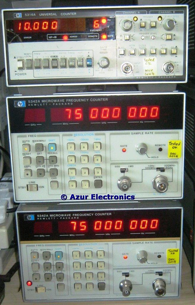
'Check' Frequencies: 5316A 10MHz; 5342A's 75MHz