Welcome to
Azur Electronics
Azur Electronics
REPAIR HP 1980B OSCILLOSCOPE
Home
Projects
Test Equipment
- Accessories
- Adaptors
- Amplifiers
- Attenuators
- Cables
- Frequency Counters
- Logic Analysers
- Multi-Meters
- Network Analysers
- Oscilloscopes
- Power Meters
- Power Supplies
- Prototyping Equipment
- Signal Generators
- Spectrum Analysers
- Tools
Operating Information
- Operating HP 141T
- Operating HP 1630D
- Operating HP 8175A
- Operating HP 8407A
- Operating HP 8410C
- Operating HP 8552B IF Section
- Operating HP 8553B RF Section
- Operating HP 8554B RF Section
- Operating HP 8555A RF Section
- Operating HP 8556A LF Section
- Operating HP 8594E Spectrum Analyser
- Operating HP 8901B
- Operating LeCroy 9310
Technical
- Allen Key Sizes
- High Voltage Measurement
- HP Cases
- HP Information
- HP-IB Interface Bus
- Measurement Units
- Motorola ECL
- RF Connectors
- RF Power - Voltage Conversion
For Sale
Wanted
Links
About Me
Contact Me
Site Map
January 2007
The HP 1980B Oscilloscope has the following five faults:
1. No Channel traces on screen but alpha-numeric display is OK.
2. Control knob does not function.
3. LED display does not function.
4. Fails ‘Confidence’ test.
5. Fails ‘Delay self cal’ and hangs system.
The HP 1980B Oscilloscope has the following five faults:
1. No Channel traces on screen but alpha-numeric display is OK.
2. Control knob does not function.
3. LED display does not function.
4. Fails ‘Confidence’ test.
5. Fails ‘Delay self cal’ and hangs system.
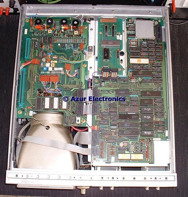
Top view with cover removed showing A3 Gate Board on left, A23 Bus
Interface Board at top middle and A4 Processor Board on the right
Interface Board at top middle and A4 Processor Board on the right
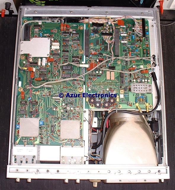
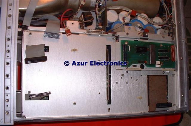
Bottom view with cover removed showing A5 Scope Board
on left and A1 Low Voltage Power Supply Board on right
on left and A1 Low Voltage Power Supply Board on right
Decided to strip everything down to assembly level for a clean-up then to check for any obvious problems and loose connections. This is a complicated beast so lots of notes and photos were required.
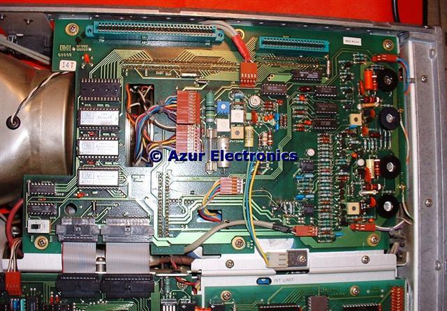
A3 Gate Board 01980-66503
The A3 Gate Board has the 4 IC sockets for the optional ROMS and there are the 2 optional digitising boards fitted vertically underneath between the CRT and side panel.
Inner Digitiser Board 19860-66501 and
Outer Digitiser Board 19860-66502
Outer Digitiser Board 19860-66502
Under the Gate Board these 2 Digitiser Boards are part of the 19860A Digital Waveform Storage option together with 2 ROMS on the A3 Board.
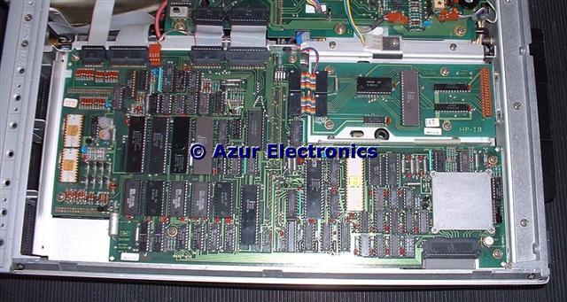
A4 Processor Board 01980-66504 and the
smaller A23 HP-IB Board 19842-66501
smaller A23 HP-IB Board 19842-66501
A1 Low Voltage Power Supply Board 01980-66535
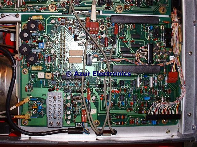
A5 Scope Board 01980-66505
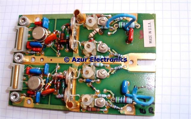
Note the Trigger Attenuator plug-in at the top left and Vertical Attenuator plug-in at the bottom left. These are each attached by 3 small screws to the pcb. Some gold contacts on the pcb and 'elastomeric' connectors on the plug-ins which can easily be damaged.
With the A1, A3, A4, A5 major boards there are there are several ribbon, wire and coax connectors on both sides of the boards, so some care is required removing them.
With the A1, A3, A4, A5 major boards there are there are several ribbon, wire and coax connectors on both sides of the boards, so some care is required removing them.
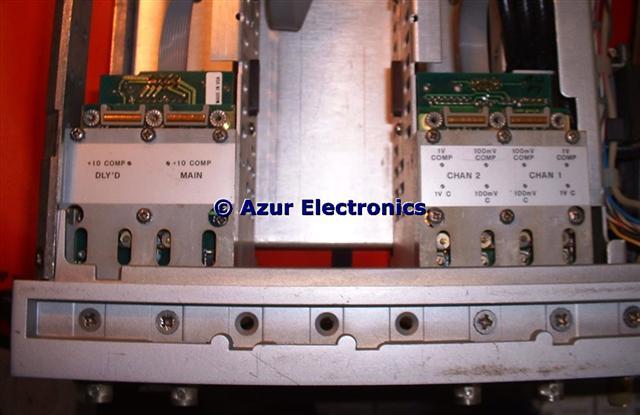
Underneath Trigger & Vertical Attenuator Plug-In's
2 Screws each in the bottom rail and the 2 plug-ins can be removed, the 4 fragile 'elastomeric' connectors can be seen on the pcbs.
A13 Vertical Attenuator Assembly
A14 Trigger Attenuator Assembly
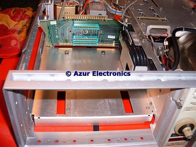
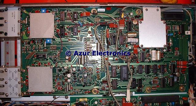
Bottom view of 3 slots for plug-ins and
optional expansion units 1950A or 1965A
optional expansion units 1950A or 1965A
The black coil of cable in the middle is A10 Delay Line Assembly.
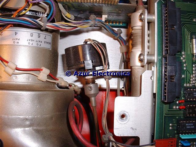
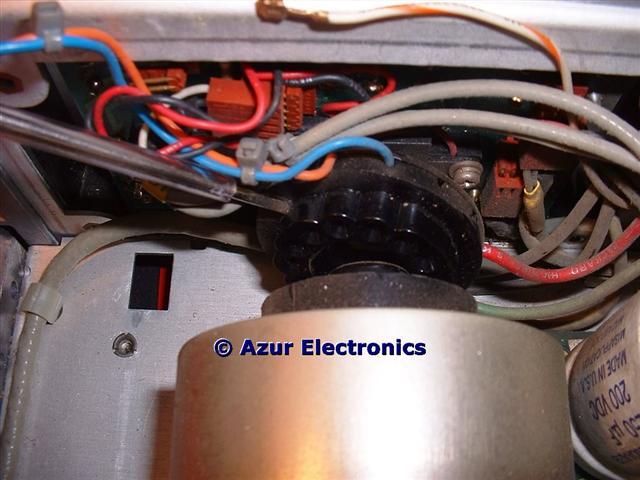
Under A3 Gate Board Assembly
This shows the RPG (Rotary Pulse Generator) on a bracket and to the right PA (Post Anode) connector and bracket.
Under A4 Processor Board Assembly
The transistor mounted on the chassis is part of the high voltage oscillator circuit.
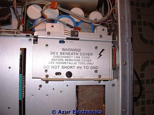
Under A23 HP-IB Board Assembly
This shows the High Voltage cover and part of mains transformer.
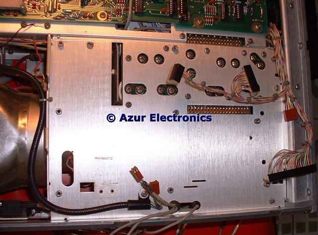
Under A1 Low Voltage Power Supply Board Assembly
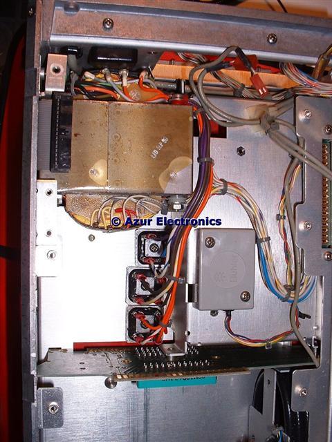
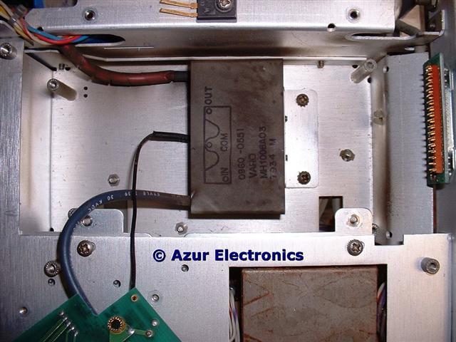
Under rear of A5 Scope Board Assembly
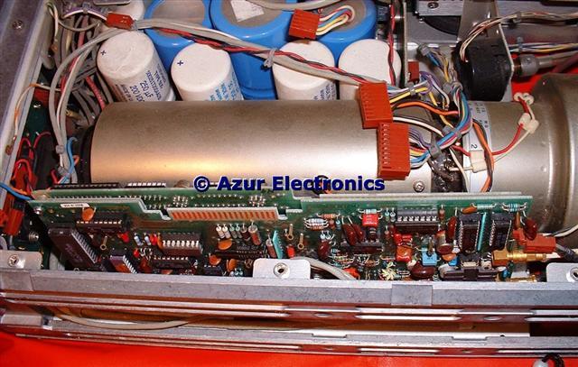
This shows the Mains Transformer, 3 Bridge Rectifiers, and cabling to connector to A7 Capacitor Board Assembly. Also unknown device in grey box marked "Buhler"?
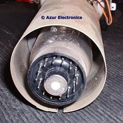
Details of A20 Cathode Ray Tube Assembly
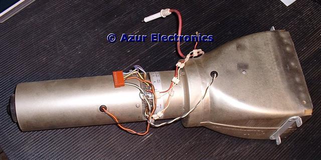
The CRT, end and neck pins are very fragile take care!
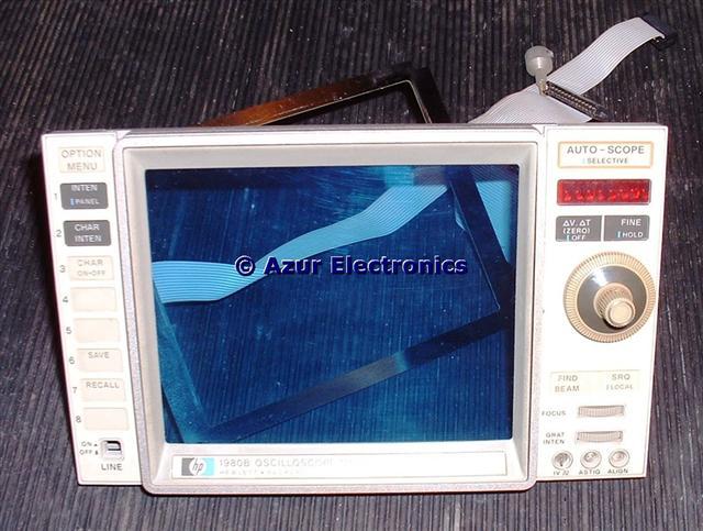
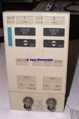
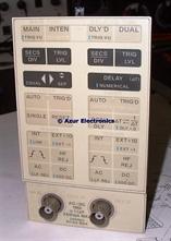
Front of A16 Display Panel Assembly and A17 Voltage Panel Assembly
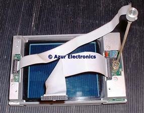
Rear view of Front of A16 Display Panel Assembly
and A17 Voltage Panel Assembly
and A17 Voltage Panel Assembly
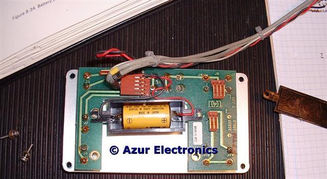
A12BT1 Battery Assembly
This is located behind the BNC connectors on the Rear Panel. The battery is still working at 3.26V with a date code of 78/11!
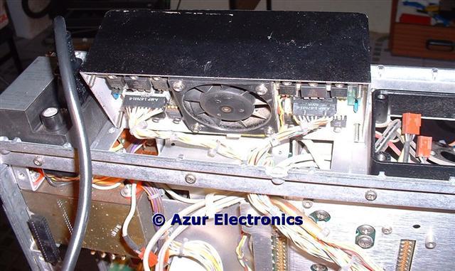
Connections to A9 Fan and Heatsink Assembly
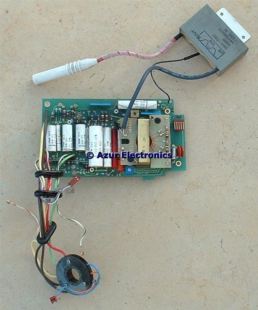
A2 High Voltage Power Supply Board Assembly
A11 High Voltage Multiplier Assembly
DANGER: Nominal +2.75kv input and +16kV output to the post anode connector.
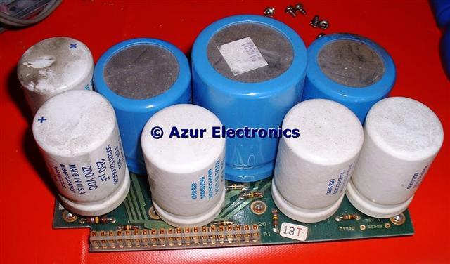
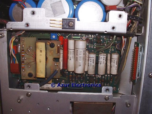
A7 Capacitor Board Assembly
With everything stripped down to Assembly level, all the parts were cleaned up and inspected. All the cabling was tested for continuity and insulation. The mains transformer, bridge rectifiers and reservoir capacitors were all tested with 230V ac applied. The mains transformer has 9 secondary windings!
March 2007
March 2007
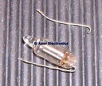
The A2 High Voltage Power Supply Board Assembly and A11 High Voltage Multiplier Assembly were very dirty and one of the neon lamps V1 has a broken wire.
The neon lamps are used to limit the maximum voltage in case of breakdown of another part. The impedance of a neon lamp is very high until it reaches its breakdown voltage of 90Vdc. This was replaced with a new neon lamp.
The neon lamps are used to limit the maximum voltage in case of breakdown of another part. The impedance of a neon lamp is very high until it reaches its breakdown voltage of 90Vdc. This was replaced with a new neon lamp.
The A15 Control Panel Assembly was stripped down to find the cause of the LED display not working.
The "Find Beam" control was open-circuit, this had a dry joint which was resoldered.
The LED display was powered up with 12Vdc and a resistor, all segments worked ok so the fault is elsewhere.
All the other switches, lamps and variable resistors were ok.
The A13, A14, A16, A17, A18 assemblies were also tested as far as possible.
April 2007
The Manual recommends cleaning the attenuators in the A13 Vertical Attenuator and the A14 Trigger Attenuator. This is a very tricky procedure and involves stripping down both units and cleaning all the relay armatures in isopropyl alcohol.
The Manual recommends cleaning the attenuators in the A13 Vertical Attenuator and the A14 Trigger Attenuator. This is a very tricky procedure and involves stripping down both units and cleaning all the relay armatures in isopropyl alcohol.
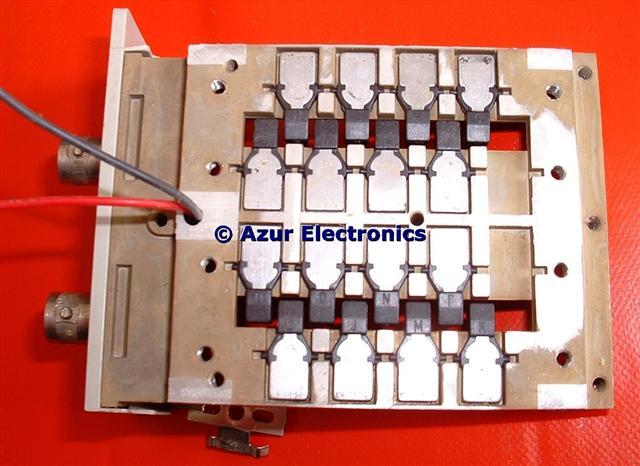
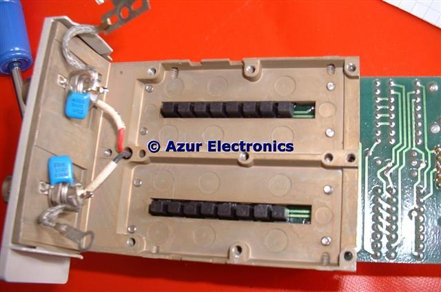
All the relays are processor controlled and
the armatures are all individually lettered
the armatures are all individually lettered
This is a seriously complicated arrangement!
The 1980B is very different to the conventional rotary switch method used in most analogue oscilloscopes. These photos are of the Vertical Attenuator and the Trigger Attenuator is very similar.
The 1980B was now re-assembled for testing. Powered-up on a Variac and no traces or data! Tested A1 low voltage power rails and all ok. Tested A2 high voltage power supply and after a few minor issues with understanding the circuitry all ok. Found a couple of connectors that had been inadvertantly swopped over from A1 and A3 and now have alpha-numeric character display again on the CRT.
The Oscilloscope is now back to the original position of 5 faults (listed at top of page).
Spent some time revising oscilloscope and CRT theory. Measured all the connections to the CRT and high voltage circuitry. Testing the A19 Rotary Pulse Generator (RPG) Assembly revealed no output. There is a good description of the RPG in HP's 'Bench Briefs' of 2nd Quarter 1987.
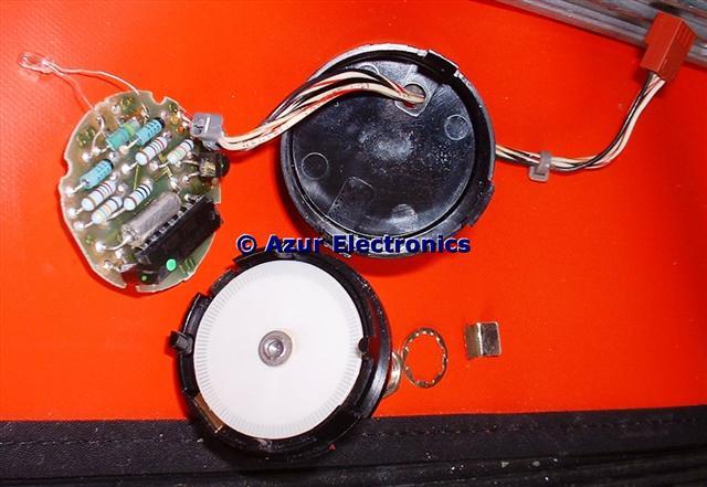
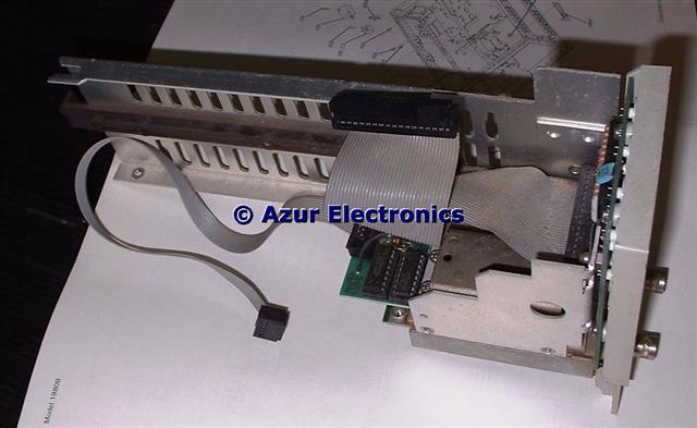
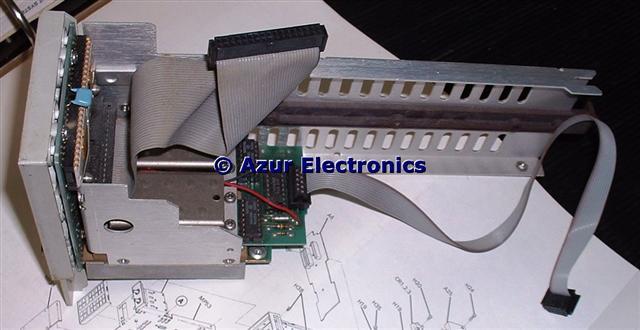
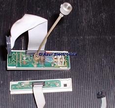
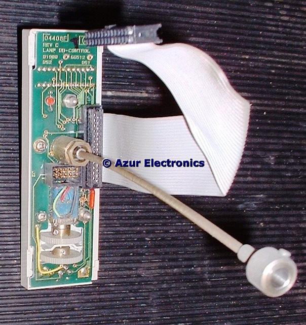
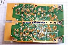
Rotary Pulse Generator
The small bulb inside the RPG had failed, this drives the photo-sensitive resistors. A small torch produced an output signal. I tried replacing the bulb with a LED but it needs a bright side-emitting output, so fitted a new bulb. Initially the RPG would only count up, not down. This was traced to only having Channel 1 output, not the 90° phase shifted Channel 2 output. This was due to the bulb being slightly mis-aligned, a small piece of blu-tack solved this! The RPG is now working correctly.
May 2007
Started work on checking the circuits around the LED Display. This is driven by a DAC on one side with a shift register on the other side, this all needs testing and a logic analyser would be useful. The dc supply varies with panel intensity, surprisingly this is not smoothed and has a high ripple content.
Now have traces on the CRT although frustratingly intermittant and most vertical and horizontal functions can be controlled but well out of specification.
... nearly 3 years later ...
April 2010
After being held up by other priorities, have now re-read the HP 1980B Operating and Programming Manual. On power-up, Autoscope selects channel 1 and main timebase but get "signal not found" message even though the probe and 1V calibration squarewave are ok. Other functions seem ok except for the LED display. Still fails confidence test as signal not found. Setting the rear panel switch to cal unprotected allows the "Front Panel Calibration Routine" to be run. Most of the tests are ok, except channel 2 can not be adjusted, the 1V cal signal can now be displayed and the 1980B now passes the "Confidence Test" ok.
Further work on the LED display circuits on A4 Processor Board and found that IC U2 (1826-0138 LM339N Quad Comparator) has failed, this provides the clock and signal inputs to the shift register U1. Swopping this IC with U12 has caused other problems and back to no trace or controls this time. One gate of U12 has also failed, this provides the reset input to the processor so everything is off. Maybe this was the earlier cause of intermittant operation, also this part of the circuit had been modified. Replaced all 3 LM339N's (U2, U12 & U44) and the oscilloscope is working again with a correctly working LED display.
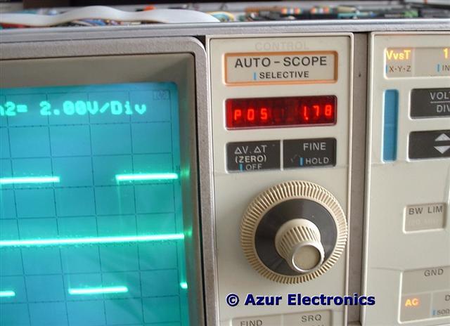
Now working display
May 2010
The fault with channel 2 was traced to A5 U7 which is a custom LSI vertical pre-amplifier (1NA2-8002). Fortunately I had a substitute IC from the HP 1950A Plug-In to verify this fault, so channels 1 & 2 are now working correctly. Apparently there are 17 custom IC's in the 1980B so if any of these fail, the only solution is a second unit for spares.
This completes the repair of this Oscilloscope.