Welcome to
Azur Electronics
Azur Electronics
REPAIR HP 141T DISPLAY SECTION
Home
Projects
Test Equipment
- Accessories
- Adaptors
- Amplifiers
- Attenuators
- Cables
- Frequency Counters
- Logic Analysers
- Multi-Meters
- Network Analysers
- Oscilloscopes
- Power Meters
- Power Supplies
- Prototyping Equipment
- Signal Generators
- Spectrum Analysers
- Tools
Operating Information
- Operating HP 141T
- Operating HP 1630D
- Operating HP 8175A
- Operating HP 8407A
- Operating HP 8410C
- Operating HP 8552B IF Section
- Operating HP 8553B RF Section
- Operating HP 8554B RF Section
- Operating HP 8555A RF Section
- Operating HP 8556A LF Section
- Operating HP 8594E Spectrum Analyser
- Operating HP 8901B
- Operating LeCroy 9310
Technical
- Allen Key Sizes
- High Voltage Measurement
- HP Cases
- HP Information
- HP-IB Interface Bus
- Measurement Units
- Motorola ECL
- RF Connectors
- RF Power - Voltage Conversion
For Sale
Wanted
Links
About Me
Contact Me
Site Map
August 2008
The HP 141T Display Section is a heavy beast at 18kg approx so handling has to be careful to avoid damage to the CRT. Testing of this equipment started with removing all the covers and giving everything a good clean. Years of dust sucked in by the fan unit had covered many of the parts.
The HP 141T Display Section is a heavy beast at 18kg approx so handling has to be careful to avoid damage to the CRT. Testing of this equipment started with removing all the covers and giving everything a good clean. Years of dust sucked in by the fan unit had covered many of the parts.
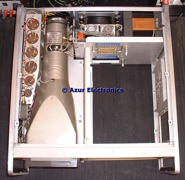
Top view with the covers removed
DANGER: High Voltages exposed
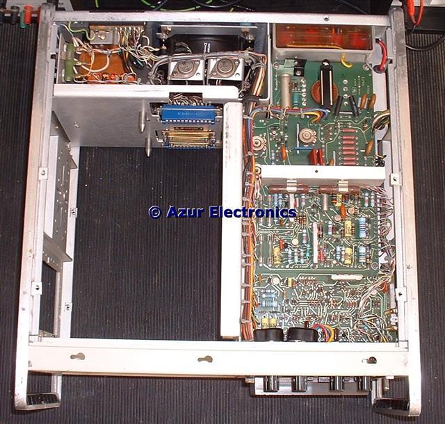
Bottom view with the covers removed
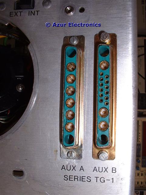
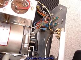
Checking for continuity & insulation for the Rear Panel contacts on Aux A & B to the connectors J9 & J11 to the plug-in units revealed a fault on Aux A contact A7. This is the Blanking/Zero Scan signal which is required by the 8443A Tracking Generator, but not the 8444A Tracking Generator.
Access to the back of this connector involves stripping down the Side Panels and Rear Panel, not easy! In particular the Transformer Assembly and Fan/Heatsink Assembly have to be removed from the Rear Panel. Not too difficult to take off but a lot trickier to put back (plenty of notes and photos required).
The coaxial contact had sheared off at the rear due to mechanical stress from the cableform to the CRT base being incorrectly routed. Luckily there was enough of the centre pin showing for short wires to be soldered to the pin and shell of the connector and what was left of the coaxial cable. As this coax is not carrying a RF signal, this repair should be ok.
Aux A bottom left coaxial
contact has sheared off
contact has sheared off
Reassembly and then powering up on a Variac showed the correct current consumption at 230Vac but the fan was not running even with 115Vac across it.
Taking the fan out is not so difficult and bench tests had the fan working again although with some reluctance to start and noisy. Removing the circlip and disc at the back of the fan allowed the fan to move off the shaft slightly but not completely even with a squirt of WD40 oil.
Taking the fan out is not so difficult and bench tests had the fan working again although with some reluctance to start and noisy. Removing the circlip and disc at the back of the fan allowed the fan to move off the shaft slightly but not completely even with a squirt of WD40 oil.
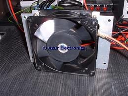
These fans are sealed units and not designed for any maintenance. A press was used to push the fan back onto the shaft but not as far as the orginal position. Even so the fan now started properly and was much quieter, although not a very high-tech solution! A replacement 120mm fan will be bought as this fan is likely to fail at some point.
Checking continuity for all contacts on the 'blue' Amphenol 24 way sockets (J1 lower & J2 upper) to various points in the circuits, and then measuring voltages when powered up, confirmed correct operation.
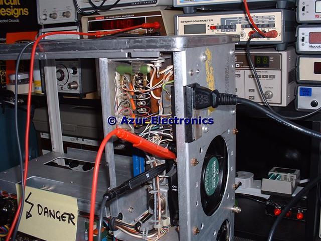
Without any plug-in units fitted there is no trace on the CRT as the X & Y deflection signals are provided by the RF Unit & IF Unit respectively. With a 8555A & 8552B fitted a trace is displayed. Initial 'Operator's Checks' for the 8555A show that the Spectrum Analyser is functioning. Adjustments to the 141T can not correctly be made without the plug-ins. Low voltage PSU adjustments were made for +100V, -100V, +248V & -12.6V. Amazing how stable these supply rails are for a 35 year old item of test equipment.
Checking the high voltage -2,350V, -2,450V and setting the intensity limit are better done with a modern 1,000:1 High Voltage Probe. See High Voltage Measurements. As everything appears to be now working ok, I didn't check the +6,600V supply or adjust the pulse circuits for the CRT Storage mode.
January/February 2009
Wanted to use the Spectrum Analyser to test some cables, so switched on and no display! Although the fault was traced to the 8552B IF Section, it affected the high voltage power supply A2 Assembly. The Unblanking input from the 8552B should be a 100V +ve going pulse which varies depending on the position of the Base Line Clipper control. Without this pulse, there is no display. In the fault condition only +18V was provided. Interestingly, when the high voltage probe loaded the control grid line at 2.4kV this produced a bright trace. The separate Blanking input drives the relay and comes from the pulse circuit of the 141T when the display is in storage mode.
Checking continuity for all contacts on the 'blue' Amphenol 24 way sockets (J1 lower & J2 upper) to various points in the circuits, and then measuring voltages when powered up, confirmed correct operation.
Without any plug-in units fitted there is no trace on the CRT as the X & Y deflection signals are provided by the RF Unit & IF Unit respectively. With a 8555A & 8552B fitted a trace is displayed. Initial 'Operator's Checks' for the 8555A show that the Spectrum Analyser is functioning. Adjustments to the 141T can not correctly be made without the plug-ins. Low voltage PSU adjustments were made for +100V, -100V, +248V & -12.6V. Amazing how stable these supply rails are for a 35 year old item of test equipment.
Checking the high voltage -2,350V, -2,450V and setting the intensity limit are better done with a modern 1,000:1 High Voltage Probe. See High Voltage Measurements. As everything appears to be now working ok, I didn't check the +6,600V supply or adjust the pulse circuits for the CRT Storage mode.
January/February 2009
Wanted to use the Spectrum Analyser to test some cables, so switched on and no display! Although the fault was traced to the 8552B IF Section, it affected the high voltage power supply A2 Assembly. The Unblanking input from the 8552B should be a 100V +ve going pulse which varies depending on the position of the Base Line Clipper control. Without this pulse, there is no display. In the fault condition only +18V was provided. Interestingly, when the high voltage probe loaded the control grid line at 2.4kV this produced a bright trace. The separate Blanking input drives the relay and comes from the pulse circuit of the 141T when the display is in storage mode.