
Welcome to
Azur Electronics
Azur Electronics
Home
Projects
Test Equipment
- Accessories
- Adaptors
- Amplifiers
- Attenuators
- Cables
- Frequency Counters
- Logic Analysers
- Multi-Meters
- Network Analysers
- Oscilloscopes
- Power Meters
- Power Supplies
- Prototyping Equipment
- Signal Generators
- Spectrum Analysers
- Tools
Operating Information
- Operating HP 141T
- Operating HP 1630D
- Operating HP 8175A
- Operating HP 8407A
- Operating HP 8410C
- Operating HP 8552B IF Section
- Operating HP 8553B RF Section
- Operating HP 8554B RF Section
- Operating HP 8555A RF Section
- Operating HP 8556A LF Section
- Operating HP 8594E Spectrum Analyser
- Operating HP 8901B
- Operating LeCroy 9310
Technical
- Allen Key Sizes
- High Voltage Measurement
- HP Cases
- HP Information
- HP-IB Interface Bus
- Measurement Units
- Motorola ECL
- RF Connectors
- RF Power - Voltage Conversion
For Sale
Wanted
Links
About Me
Contact Me
Site Map
HP 11592-60015 PLUG-IN EXTENDER ASSEMBLY
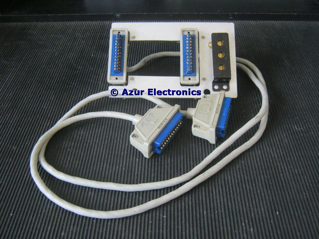
Front view showing connectors and resistor
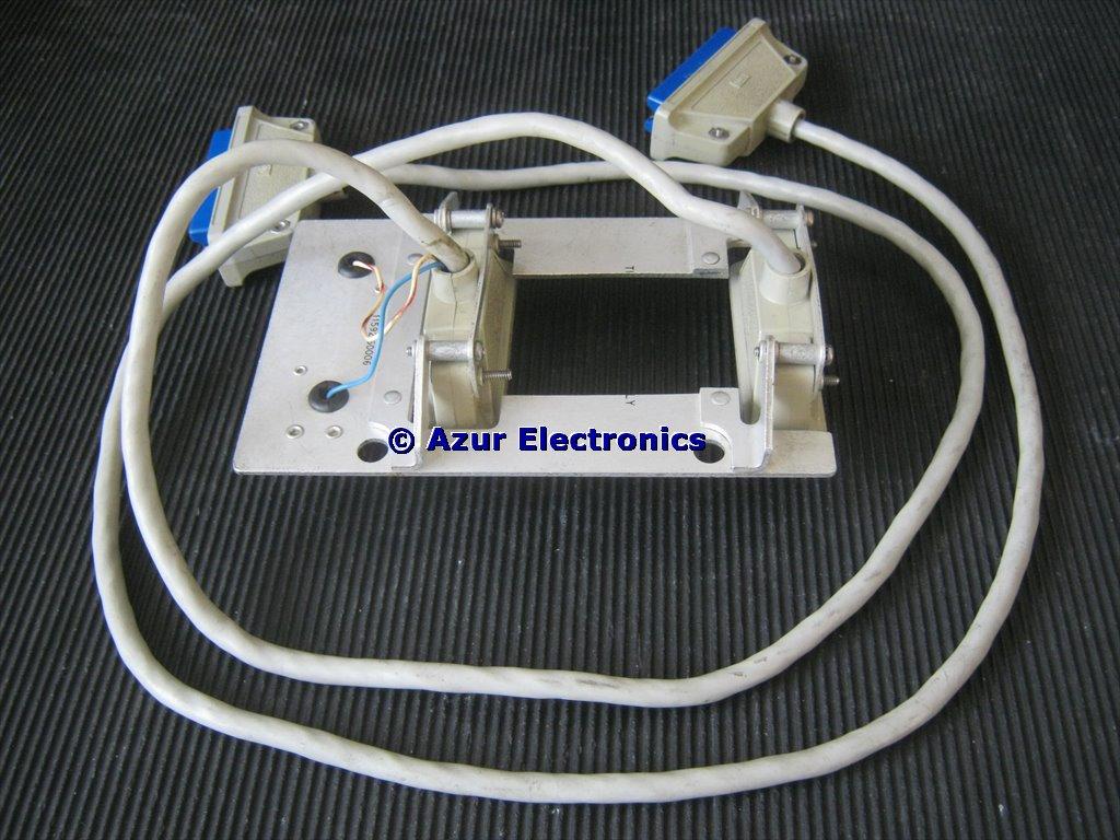
Rear view showing connectors and wiring to resistor
This Extender is part of the HP 08555-60077 Service Kit which I have been looking for as a useful accessory for some time, but I have never seen one on eBay. These special cables are available from GLK Instruments, plus there is an HP 11592-60016 Inter-Connecting Cable between the RF & IF Sections, both very expensive though!
July 2018
I was given the Extender in exchange for some HP Case parts (thanks Paul). It needed cleaning-up, some wires resoldered and testing by buzzing out end to end. Although all pin to pin wiring, there is a capacitor and a link in the RF cable and a resistor in the IF cable. The capacitor is a 470nF Z5U disc ceramic and is across the horizontal deflection circuit. The link is on the +100V circuit. The resistor is a 182Ω 50W wirewound as a current limiter on the +100V supply.
The cable ends attached to the metal plate and bracket fit inside the 141T, the RF Section at the top and the IF Section at the bottom. There is a cut-out in the metal plate to fit the 2 Special D-Type connectors to the external connections, see HP 141T Display Section External Connections.
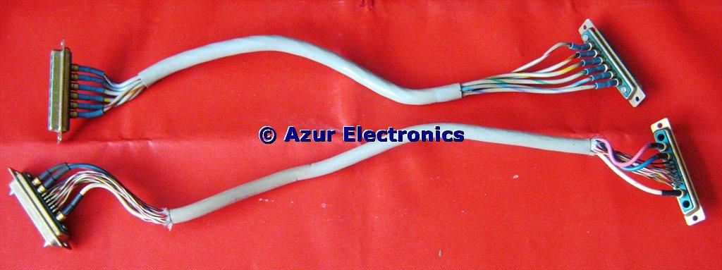
2 Special D-Type Connecting Cables
These 2 Special D-Type Connecting Cables came from a dismantled HP 141T Display Section. As the cables are simply routed directly to the Rear Panel of the 141T, a direct connection to the external equipment (AUX A is connected to either the HP 8443A Tracking Generator Counter or the HP 8444A Tracking Generator and AUX B is connected to the HP 8445B Automatic Preselector) could be made instead. That is probably easier as these 2 cables are not really long enough!
RF Cable Connections
| Pin No | Wire Colour | Wire Number | Notes |
|
1 |
BL | 6 | |
| 2 | WH/RD | 92 | Wire Link to Pin 16 |
| 3 | WH/RD/YL | 924 | |
| 4 | WH/YL/GN | 945 | |
| 5 | n.c. | ||
| 6 | VL | 7 | |
| 7 | n.c. | ||
|
8 |
WH/GN/GY | 958 | |
| 9 | RD | 2 | |
| 10 | WH/BK/RD | 902 | |
| 11 | WH/BK/GN | 905 | |
| 12 | WH | 9 | 470nF Capacitor |
| 13 | BN | 1 | |
| 14 | n.c. | ||
| 15 | n.c. | ||
| 16 | WH/RD/BL | 926 | Wire Link to Pin 2 |
| 17 | n.c. | ||
| 18 | WH/BK | 90 | |
| 19 | n.c. | ||
| 20 | n.c. | ||
| 21 | WH/VL | 97 | |
| 22 | WH/BK/YL | 904 | |
| 23 | WH/BK/BL | 906 | |
| 24 | GN | 5 | 470nF Capacitor |
There is an additional WH/RD 92 wire cut-off at both ends.
IF Cable Connections
| Pin No | Wire Colour | Wire Number | Notes |
|
1 |
BL | 6 | 182Ω 50W Resistor |
| 2 | n.c. |
|
182Ω 50W Resistor |
| 3 | WH/RD/YL | 924 | |
| 4 | WH/YL/GN | 945 | |
| 5 | n.c. | ||
| 6 | VL | 7 | |
| 7 | n.c. | ||
|
8 |
WH/GN/GY | 958 | |
| 9 | RD | 2 | |
| 10 | WH/BK/RD | 902 | |
| 11 | WH/BK/GN | 905 | |
| 12 | WH | 9 |
|
| 13 | BN | 1 | |
| 14 | n.c. | ||
| 15 | n.c. | ||
| 16 | WH/RD/BL | 926 |
|
| 17 | n.c. | ||
| 18 | WH/BK | 90 | |
| 19 | n.c. | ||
| 20 | n.c. | ||
| 21 | WH/VL | 97 | |
| 22 | WH/BK/YL | 904 | |
| 23 | WH/BK/BL | 906 | |
| 24 | GN | 5 |
|
August 2019
Now sold.
Now sold.