
Welcome to
Azur Electronics
Azur Electronics
HP 1120A 500MHz PROBE
Home
Projects
Test Equipment
- Accessories
- Adaptors
- Amplifiers
- Attenuators
- Cables
- Frequency Counters
- Logic Analysers
- Multi-Meters
- Network Analysers
- Oscilloscopes
- Power Meters
- Power Supplies
- Prototyping Equipment
- Signal Generators
- Spectrum Analysers
- Tools
Operating Information
- Operating HP 141T
- Operating HP 1630D
- Operating HP 8175A
- Operating HP 8407A
- Operating HP 8410C
- Operating HP 8552B IF Section
- Operating HP 8553B RF Section
- Operating HP 8554B RF Section
- Operating HP 8555A RF Section
- Operating HP 8556A LF Section
- Operating HP 8594E Spectrum Analyser
- Operating HP 8901B
- Operating LeCroy 9310
Technical
- Allen Key Sizes
- High Voltage Measurement
- HP Cases
- HP Information
- HP-IB Interface Bus
- Measurement Units
- Motorola ECL
- RF Connectors
- RF Power - Voltage Conversion
For Sale
Wanted
Links
About Me
Contact Me
Site Map
The HP 1120A is used for probing signals with high source impedances at frequencies up to 500MHz. A 50Ω output is provided to interface with test equipment. A dc power supply is also required. The 1120A cost $750 in 1980.
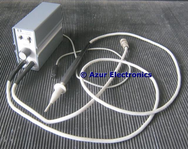
Probe and connecting cables
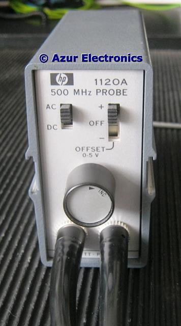
The Offset Vernier control is a 10 turn variable resistor, this is only functional in the DC switch position together with the +ve or -ve setting.
Specification
Bandwidth: dc to >500MHz dc coupled <1.5kHz to >500MHz ac coupled.
Pulse Response: <0.75ns rise time.
Gain: 1:1 ±5% active probe.
Dynamic Range: ±0.5V with ±5V dc offset.
Noise: 2.5mV approx.
Input Impedance: 100kΩ shunted by <3pF at 100MHz 1:1 Probe.
10:1 Divider shunted by <1pF at 100MHz.
Maximum Input: ±80V.
Power: +15V/0V/-12.6V from HP 1122A Probe Power Supply or from Test Equipment (HP 8553B RF Section, HP 180A Oscilloscope, etc.)
June 2011
Arrived in good condition, has HP 10229A Hook Tip fitted. Other Accessories available were: HP 10241A 10:1 Divider; HP 10243A 100:1 Divider; HP 10242A Bandwidth Limiter (27MHz 6pF). I bought this mainly to work with the HP 8553B Spectrum Analyser RF Section but it can be used with any other suitable test equipment, or with an extra power supply such as the HP 1122A.
Cleaned-up and downloaded Operating Note, dated April 1976, which includes Description, Specification, Performance Checks and Adjustments, Troubleshooting, Parts, Schematics.
Need to find a spare 3 pin plug so I can make a test cable to a Power Supply Unit.
February 2016
The 3 Pin Plug and Socket are a special HP part and not easily available, except from scrap units. I only need to be able to power it up for testing. Found a similar socket from Farnell 112-2806 (thanks Robert) which is made by Binder 09 9749 30 03. This needs modifying by cutting off some of the plastic housing to fit the plug. Take care to get the polarity correct! Powering up on a dual power supply provides +15V at 89mA and -12.6V at 55mA.
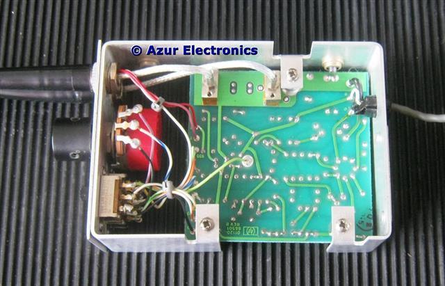
PCB component side PCB wiring side
Power supply wiring is at top right of the PCB. White is +15V, Black is -12.6V and Screen is 0V.
Initial checks and the dc & ac waveforms and the +ve & -ve offset control are both ok.
March 2016
Performance Check and Adjustments are detailed in the Operating Note. These use some obsolete test equipment, so methods needed updating. Passed ok.
August 2019
Now sold.
Initial checks and the dc & ac waveforms and the +ve & -ve offset control are both ok.
March 2016
Performance Check and Adjustments are detailed in the Operating Note. These use some obsolete test equipment, so methods needed updating. Passed ok.
August 2019
Now sold.